Transmission unit

Active Publication Date: 2011-10-13
PINION
View PDF9 Cites 28 Cited by
  • Summary
  • Abstract
  • Description
  • Claims
  • Application Information

AI Technical Summary

Benefits of technology

[0014]The object of the present invention is therefore to provide an improved transmission unit, an improved shifting device and an improved transmission housing fo

Problems solved by technology

Such derailer gearshifts offer up to thirty gearspeeds, but due to the system a large number of gearspeeds are redundant, and some gearspeeds cannot be used, or can only be used to a restricted degree, as a result of high frictional losses due to a diagonal course of the chain.
A disadvantage with the principle of the derailer gearshift is not only the large number of redundant gearspeeds and the frictional losses but also the fact that the components are exposed and are therefore subject directly to environmental influences such as water and dirt and can very easily be damaged by shocks.
A disadvantage with the principle of the hub gearshift in the rear axle is that the weight of the rotating masses is increased and, in the case of bicycles which have rear wheel suspension, the non-suspended mass is increased considered relative to the overall weight.
In addition, the center of gravity of the bicycle is displaced in

Method used


Image

  • Transmission unit
  • Transmission unit
  • Transmission unit

Examples


Embodiment Construction

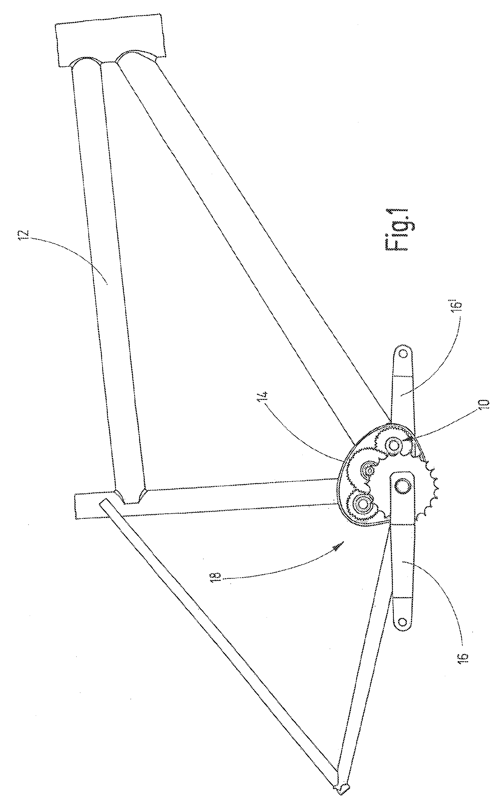
[0144]In FIG. 1, a transmission unit is denoted generally by 10.

[0145]FIG. 1 shows a side view of a bicycle frame 12 which has a transmission housing 14 in which the transmission unit 10 is held. The transmission unit 10 is only indicated schematically in this illustration and is formed as a compact unit which is preferably arranged in a transmission cage (not illustrated here). The transmission unit 10 is described here by way of example for the use in a bicycle, but the use in other vehicles which are operated by muscle force is also possible. In addition, it is also conceivable to use the transmission unit 10 for vehicles in which muscle force is used in combination with a drive machine for driving the vehicle.

[0146]The transmission unit 10 and the transmission housing 14 form, together with foot pedals 16 and 16′, a multi-gearspeed transmission 18.

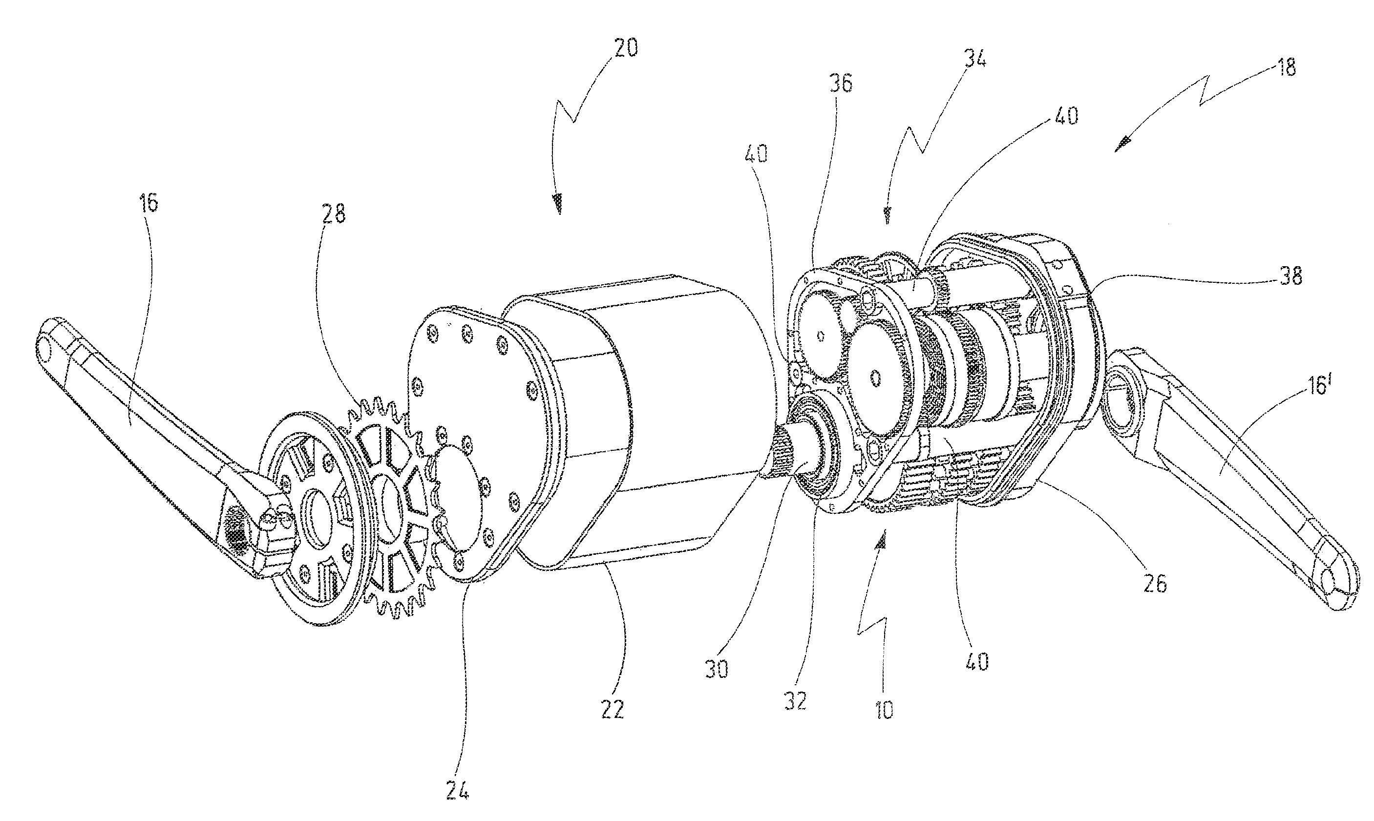
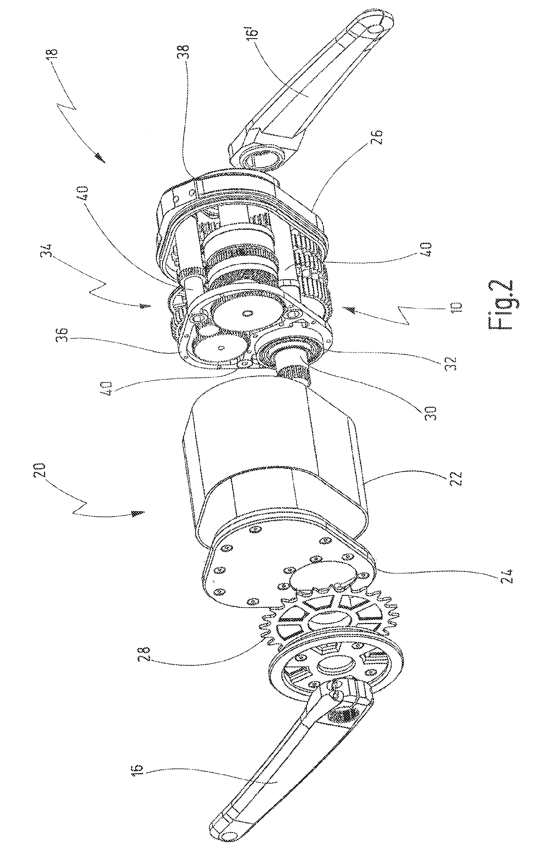
[0147]FIG. 2 shows an exploded illustration of the multi-gearspeed transmission 18. Identical components are provided with identical ...


PUM


Abstract

The present invention relates to a transmission unit for a vehicle driven by muscle force, comprising an input shaft which can be connected to cranks on opposite sides for driving the vehicle, comprising a first partial transmission. The first partial transmission comprises a countershaft, wherein a plurality of driving gear wheels is mounted on the input shaft, and wherein a corresponding plurality of driven gear wheels of the first partial transmission is mounted on the partial transmission shaft. The driven gear wheels of the first partial transmission are designed as idler gears that can be connected to the countershaft by means of shifting means in a rotationally rigid manner. The countershaft forms an input shaft of a second partial transmission. A plurality of second drive wheels are mounted on the output shaft, wherein the second partial transmission comprises an output shaft, on which a corresponding plurality of second driven gear wheels are mounted.

Description

CROSS-REFERENCE TO RELATED APPLICATIONS[0001]This application is a continuation of international Patent Application No. PCT / EP 2009 / 009193, filed Dec. 21, 2009, the complete contents of which are hereby incorporated by reference.BACKGROUND OF THE INVENTION[0002]The invention relates to a shifting device for a transmission unit of a vehicle operated by muscle force.[0003]The invention also relates to a transmission unit for a vehicle operated muscle force.[0004]The invention additionally relates to a transmission housing for a transmission unit of a vehicle driven by muscle force.[0005]Such transmission units serve to step up or step down the muscle force and as a result the provision of driving force to the vehicle.[0006]Basically, there are three types of gearshifts for vehicles or motorbikes which are driven by muscle force, specifically derailleur gearshifts, hub gearshifts and bicycle gearshifts.[0007]The derailleur gearshift has not changed significantly in the last decades. In...

Claims


Application Information

Patent Timeline
IPC IPC(8): B62M11/14F16H3/44
CPCB62M11/145Y10T74/19409B62M11/06Y10T74/19353
Inventor SCHMITZ, MICHAELLERMEN, CHRISTOPH
Owner PINION
Why Eureka
Try Eureka