
Slidable Fixation Device for Securing a Medical Implant

a fixation device and medical implant technology, applied in the direction of transvascular endocardial electrodes, electrotherapy, therapy, etc., can solve the problems of difficult or impossible to test the responsiveness of the implantation site, difficult or impossible to reposition the pacemaker without injury to the heart, and leadless stimulators or sensors from the implantation site a serious and possibly life-threatening even

Active Publication Date: 2011-10-13
MEDTRONIC VASCULAR INC
View PDF8 Cites 192 Cited by
  • Summary
  • Abstract
  • Description
  • Claims
  • Application Information

AI Technical Summary

Benefits of technology

[0005]Embodiments hereof also relate to a system for percutaneously delivering a medical implant to an implantation site and securing the medical implant at the implantation site. The system includes an outer sheath having a lumen extending there through and a medical implant held within the outer sheath lumen at a distal end thereof. A distal end of the medical implant protrudes out of the outer sheath distal end to form a distal tip of the delivery system. The system also includes a fixation device having an annular collar and an array of self-expanding tines that distally extend from the collar and are preset to splay outwardly from the medical implant and curve backward toward the collar. The fixation device is positioned proximal of the distal end of the delivery system during delivery and, if applicable, during the testing of the implantation site. The fixation device is slidably mounted on the medical implant such that the fixation device may be distally advanced over the medical implant to deploy the tines from a delivery configuration, in which the tines are constrained and substantially straightened by the outer sheath, to an expanded configuration, in which the tines are released from the outer sheath and tend to assume their preset shape.

Problems solved by technology

The potential for detachment of a leadless stimulator or sensor from an implantation site represents a serious and possibly life-threatening event.
In the case of a leadless pacemaker, such a distally placed anchoring structure makes it difficult or impossible to test the implantation site for responsiveness to determine whether that area of the heart will accept pacing pulses until after the full deployment of the anchoring structure such that an electrode of the pacemaker makes contact with the heart.
In addition, if the implantation site is determined to be unacceptable or less than optimal after deployment of the distal anchoring structure, it may be difficult or impossible to reposition the pacemaker without injury to the heart.

Method used


Image

  • Slidable Fixation Device for Securing a Medical Implant
  • Slidable Fixation Device for Securing a Medical Implant
  • Slidable Fixation Device for Securing a Medical Implant

Examples


Embodiment Construction

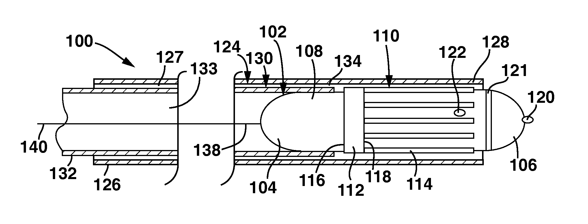
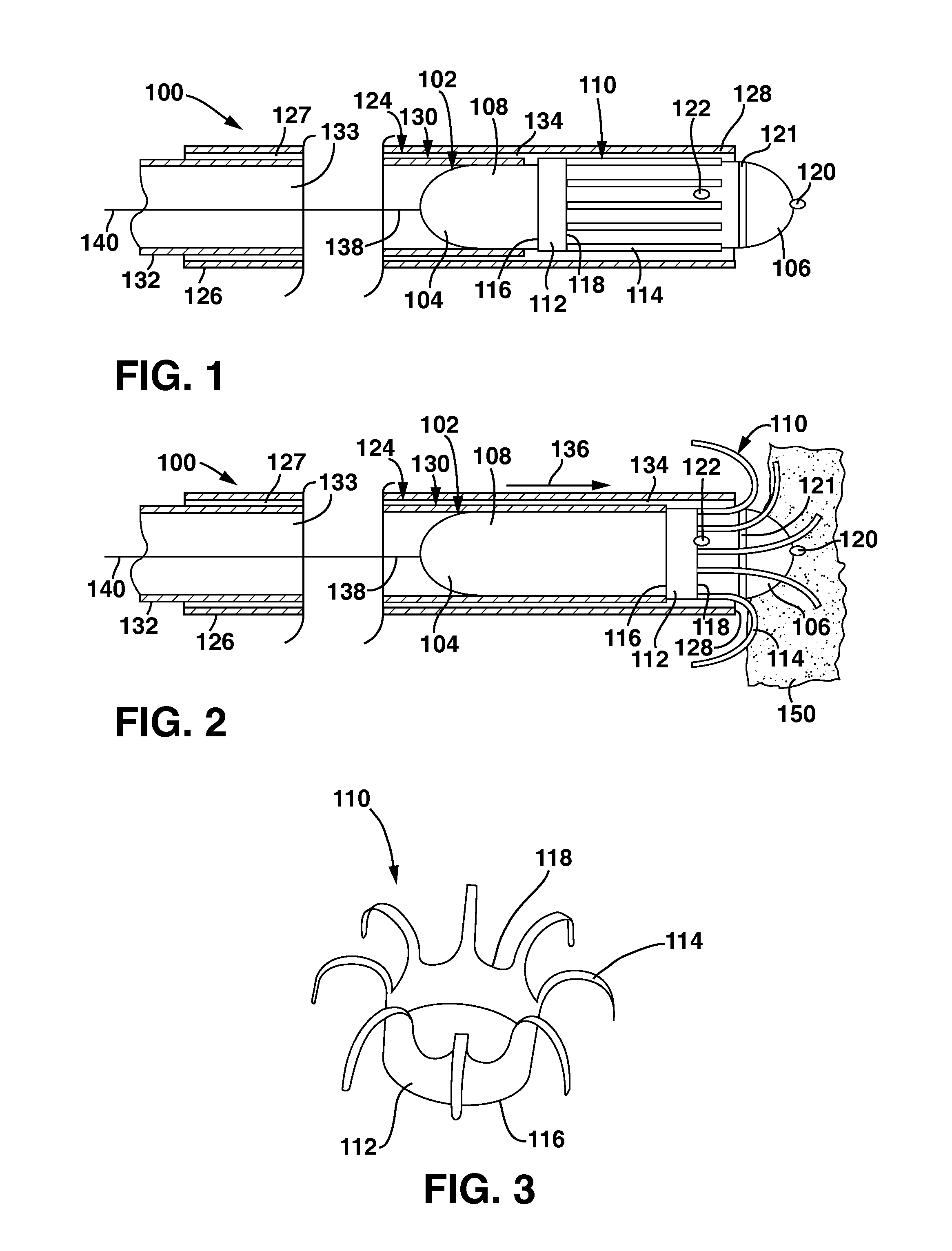
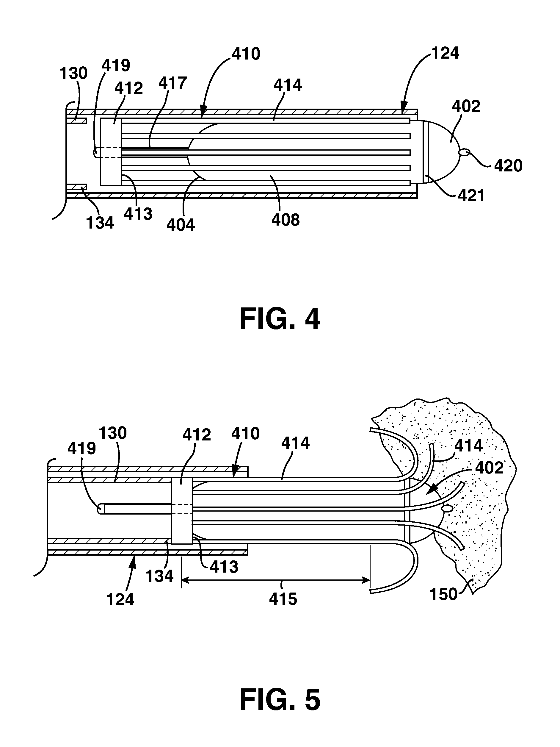
[0014]Specific embodiments of the present invention are now described with reference to the figures, wherein like reference numbers indicate identical or functionally similar elements. The terms “distal” and “proximal” are used in the following description with respect to a position or direction relative to the treating clinician. “Distal” or “distally” are a position distant from or in a direction away from the clinician. “Proximal” and “proximally” are a position near or in a direction toward the clinician.

[0015]The following detailed description is merely exemplary in nature and is not intended to limit the invention or the application and uses of the invention. Although the description of the invention is in the context of placement of a leadless pacemaker for treatment of the heart, the invention may also be adapted for use in delivering and implanting medical sensors or stimulators to other areas of a patient's body where it is deemed useful. Furthermore, there is no intention...


PUM


Abstract

A fixation device for retaining a leadless medical implant to tissue includes an annular collar and an array of self-expanding tines extending from the collar. When deployed, the annular collar encircles the implant and the tines are preset to splay outwardly from the implant to grab body tissue and anchor the implant at a treatment site. The implant and fixation device are contained within a sheath for delivery to the treatment site and a pushing force is applied to a pusher of the delivery system to distally advance the fixation device relative to the implant and deploy the tines. A distal end of the implant having an electrode may form a distal tip of the delivery system, and a potential implantation site may be tested prior to deployment of the fixation device to allow for easy repositioning of the implant if the potential implantation site is determined to be unacceptable.

Description

FIELD OF THE INVENTION[0001]The invention relates to a fixation device for securing a medical implant to tissue of the heart.BACKGROUND OF THE INVENTION[0002]Medical implants such as leadless stimulators or sensors may be surgically, or in some instances, percutaneously delivered and implanted within tissue of the heart. The potential for detachment of a leadless stimulator or sensor from an implantation site represents a serious and possibly life-threatening event. For example, a leadless pacemaker that becomes dislodged from an implantation site in the right ventricle of the heart can exit the heart via the pulmonic valve and lodge in the lung. Thus, secure fixation of leadless implants is extremely important for successful operation of the implant as well as for the safety of the patient.[0003]In order to secure the implant to tissue at the implantation site, the implant may include anchoring structure at a distal end thereof that must be screwed or otherwise engaged with tissue ...

Claims


Application Information

Patent Timeline
Patent Type & Authority Applications(United States)
IPC IPC(8): A61N1/05
CPCA61B17/3468A61N1/3756A61N1/37205A61N1/057A61N1/37518
Inventor GRISWOLD, ERIK
Owner MEDTRONIC VASCULAR INC
Features
  • Generate Ideas
  • Intellectual Property
  • Life Sciences
  • Materials
  • Tech Scout
  • Unparalleled Data Quality
  • Higher Quality Content
  • 60% Fewer Hallucinations
Learn More