Deployment system for an expandable device

a deployment system and expandable technology, applied in the field of deployable medical device assemblies, can solve the problems of reducing the profile of the sheath-expandable medical device combination, thin-walled sheaths, etc., and achieve the effect of increasing the flexibility of the distal portion and reducing the profile of the deployment system

Active Publication Date: 2005-02-10
WL GORE & ASSOC INC
View PDF98 Cites 284 Cited by
  • Summary
  • Abstract
  • Description
  • Claims
  • Application Information

AI Technical Summary

Benefits of technology

[0020] In preferred embodiments, materials, composites, constructions, and / or assemblies exhibiting compliance, compressibility, resilience, and / or expandability are placed between the endoluminal device and the delivery catheter to provide an “endoprosthesis mounting member.” An endoprosthesis mounting member serves to cushion the expandable medical device when constrained by the sheath and may assist in expansion of the device when unconstrained. An endoprosthesis mounting member also serves to anchor and retain the expandable medical device in place around an underlying catheter shaft. Anchoring the expandable medical device with an endoprosthesis mounting member eliminates the need for barrier, or retention, means at either end of the expandable medical device. The absence of barrier means contributes to a reduction in the profile of the deployment system as well as increasing the flexibility of the distal portion of the system. The present invention can also be provided with an additional catheter or catheter lumen for the sheath-deployment line in order to prevent the deployment line portion from leaving the general path established by the delivery catheter. The preferred endoprosthesis mounting member is in the form of an inflatable, or otherwise expandable, balloon. The present invention can also be used alone or in combination with other expandable medical device delivery means. Multiple expandable medical devices can also be delivered with the present invention.

Problems solved by technology

The thin-walled sheath also reduces the profile of the sheath-expandable medical device combination, when compared to conventional constraints.

Method used


Image

  • Deployment system for an expandable device
  • Deployment system for an expandable device
  • Deployment system for an expandable device

Examples


example 1

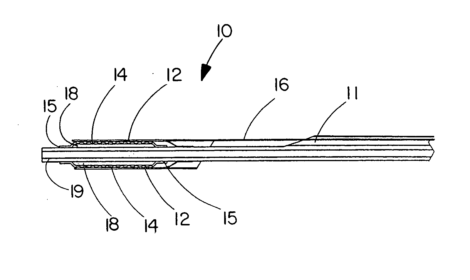
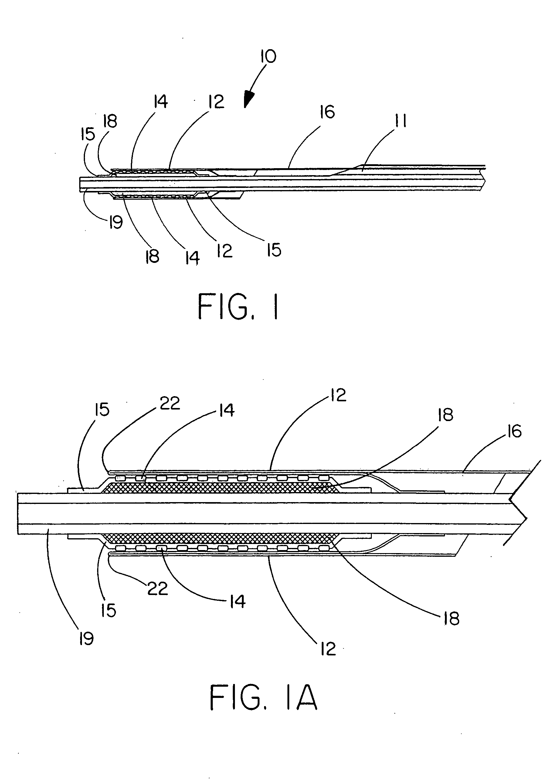
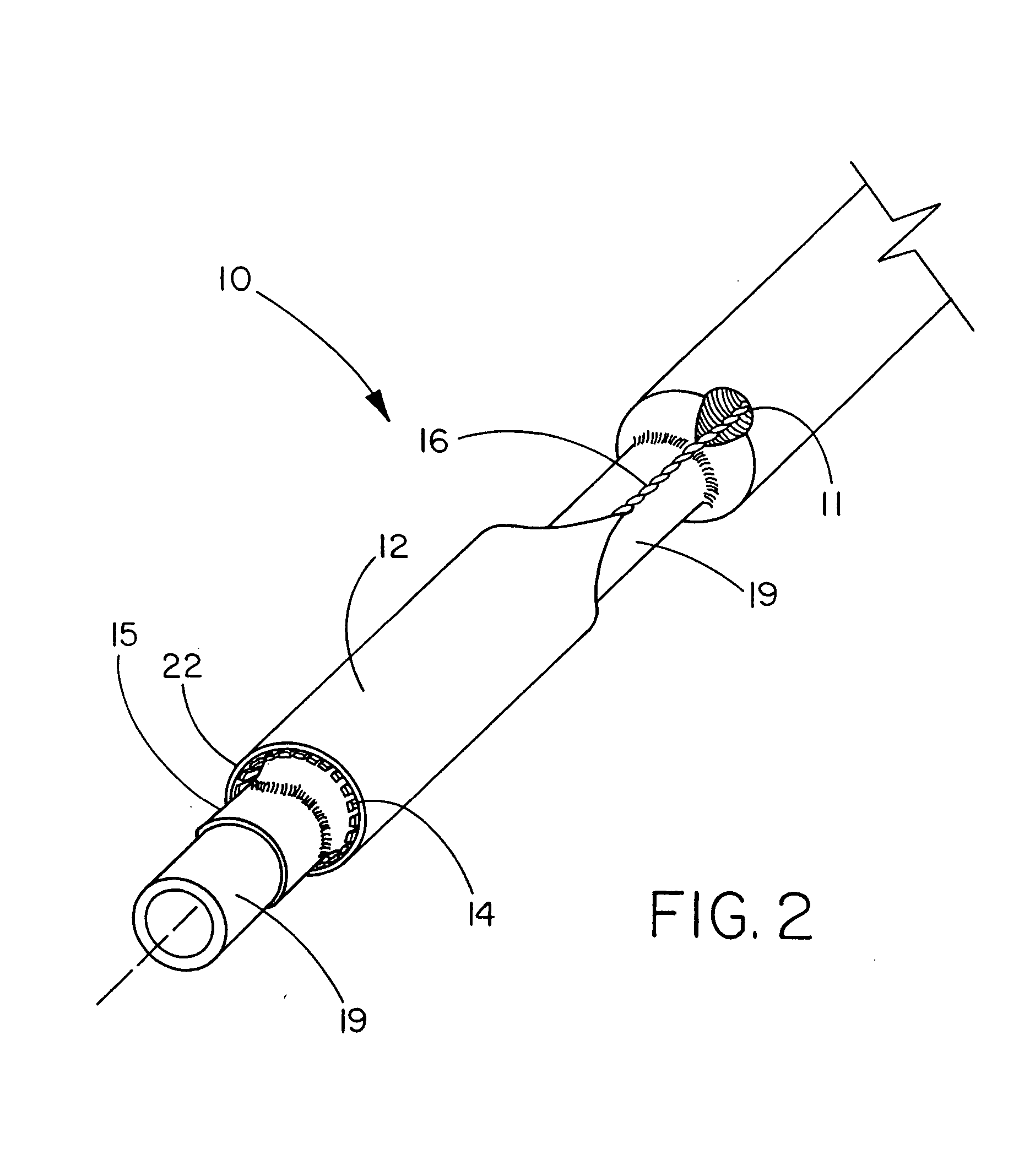
[0073] This example describes the construction of a deployment system of the present invention. Construction of the system began with the preparation of a distal catheter shaft for receiving an expandable stent. Once the distal catheter was prepared, the expandable stent was placed within a sheath-deployment line. The distal catheter portion of this combination was attached to a primary catheter shaft. The deployment line portion was then routed through the primary catheter to a control knob. The control knob was part of a hub located proximally on the primary catheter. The sheath portion of the sheath-deployment line was in the form of a single-walled tube.

[0074] A tubular material three inches long was obtained from Burnham Polymeric, Inc., Glens Falls, N.Y. for use as the distal catheter shaft. The tube was made of a polyether block amide material, commonly known as PEBAX® resin and reinforced with a stainless steel braid. The outer diameter (OD) was 1.01 mm and the inner diamet...

example 2

[0085] This example describes the construction of a deployment system of the present invention. Construction of the system begins with the preparation of a distal catheter shaft for receiving an expandable stent. Once the distal catheter was prepared, the expandable stent was placed within a sheath-deployment line. The distal catheter portion of this combination was attached to a primary catheter shaft. The deployment line portion was then routed through the primary catheter to a control knob. The control knob was part of a hub located proximally on the primary catheter. The sheath portion of the sheath-deployment line was in the form of a double-walled tube.

[0086] A tubular material three inches long was obtained from Burnham Polymeric, Inc., Glens Falls, N.Y. for use as the distal catheter shaft. The tube was made of a polyether block amide material, commonly known as PEBAX® resin and reinforced with a stainless steel braid. The outer diameter (OD) was 1.01 mm and the inner diame...

example 3

[0090] This example describes the incorporation of a means for initiating or maintaining conversion of the sheath portion of the sheath-deployment line to deployment line by introducing perforations and intentional stress risers into the sheath.

[0091] The sheath-deployment line from Example 2 is modified as follows. Prior to rolling the sheath portion into a double-walled construct and loading the stent therein, the sheath is perforated and / or supplied with “stress risers” that facilitate in separation of the tubular sheath upon retraction of the deployment line portion. An appropriate laser for making the perforations or stress risers is a 20 watt CO2 laser obtained from Universal Laser Systems, Scottsdale, Ariz. To form the perforations in the sheath portion, the sheath is placed on a sandblasted stainless steel mandrel and exposed to the laser to cut a series of holes in a part of the tube that will subsequently serve as the outer wall of the double-walled construct. The geometr...


PUM


Abstract

The present invention is directed to a deployment system for an endoluminal device. The deployment system includes a confining sheath placed around a compacted endoluminal device. A deployment line is provided in the system that is an integral extension of the sheath. As the deployment line is actuated, the sheath retracts from around the compacted endoluminal device. As the sheath retracts from around the endoluminal device, material from the sheath may be converted into deployment line. Once the sheath is retracted from around the compacted endoluminal device, the endoluminal device expands in configuration and repairs vascular or cardiac structures of an implant recipient. Any remaining sheath material is removed from the implantation site along with the deployment line. The deployment system also includes an endo-prosthesis mounting member placed between the endoluminal device and an underlying catheter. The endo-prosthesis mounting member serves to cushion and retain the endoluminal device when constrained by the sheath and may assist in expansion of the endoluminal device when unconstrained by the sheath. The present invention is also directed to a deployment system having a deployment assembly that simultaneously expands an endo-prosthesis mounting member while removing a sheath from an expandable medical device.

Description

CROSS REFERENCE TO RELATED APPLICATIONS [0001] This application is a continuation-in-part of co-pending application Ser. No. 10 / 637,986, filed Aug. 8, 2003, which is a continuation-in-part of co-pending application Ser. No. 10 / 346,598, filed Jan. 17, 2003.FIELD OF THE INVENTION [0002] The present invention relates generally to implantable medical device assemblies. In particular, the invention relates to means for deploying an expandable medical device within vascular or cardiac structures of an implant recipient. BACKGROUND OF THE INVENTION [0003] Various implantable medical devices for repairing or reinforcing cardiac and vascular structures have been developed in recent years. Some of these devices can be implanted inside a particular vascular or cardiac structure through so-called interventional, or endovascular, techniques. Interventional techniques involve surgically accessing the vascular system through a conveniently located artery or vein and introducing distal portions of ...

Claims


Application Information

Patent Timeline
Patent Type & Authority Applications(United States)
IPC IPC(8): A61F2/06A61F2/84
CPCA61F2/95A61F2/958A61F2002/9511A61F2/97A61F2/966A61F2/9662
Inventor CULLY, EDWARD H.FLURY, KEITH M.VONESH, MICHAEL J.
Owner WL GORE & ASSOC INC
Why Eureka
Try Eureka