Valve prosthesis

a valve and prosthesis technology, applied in the field of anatomical valve replacement devices, can solve the problems of mitral valves preventing direct application of current aortic/pulmonary technology, insufficiency of valves, and increase in the incidence of mitral regurgitation

Active Publication Date: 2012-11-29
THE TRUSTEES OF THE UNIV OF PENNSYLVANIA
View PDF4 Cites 284 Cited by
  • Summary
  • Abstract
  • Description
  • Claims
  • Application Information

AI Technical Summary

Problems solved by technology

Pathologic changes in any of these structures can lead to valvular insufficiency.
The incidence of mitral regurgitation increases with age and is a frequent clinically significant medical problem in the post MI population and patients with COPD.
While there is a great deal of interest in replacing the mitral valve percutaneously (not least because many patients that have suffered myocardial infarction are not fit for surgical valve replacement) the anatomy and function of the mitral valve prevents direct application of the current aortic / pulmonic technology.

Method used


Image

  • Valve prosthesis
  • Valve prosthesis
  • Valve prosthesis

Examples


embodiment i

General Embodiment I

[0029]The following disclosure pertains to a first general embodiment of the present disclosure, which pertains to inventive valve prostheses and methods for replacing a damaged or diseased valve.

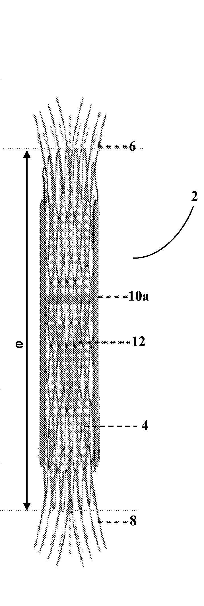
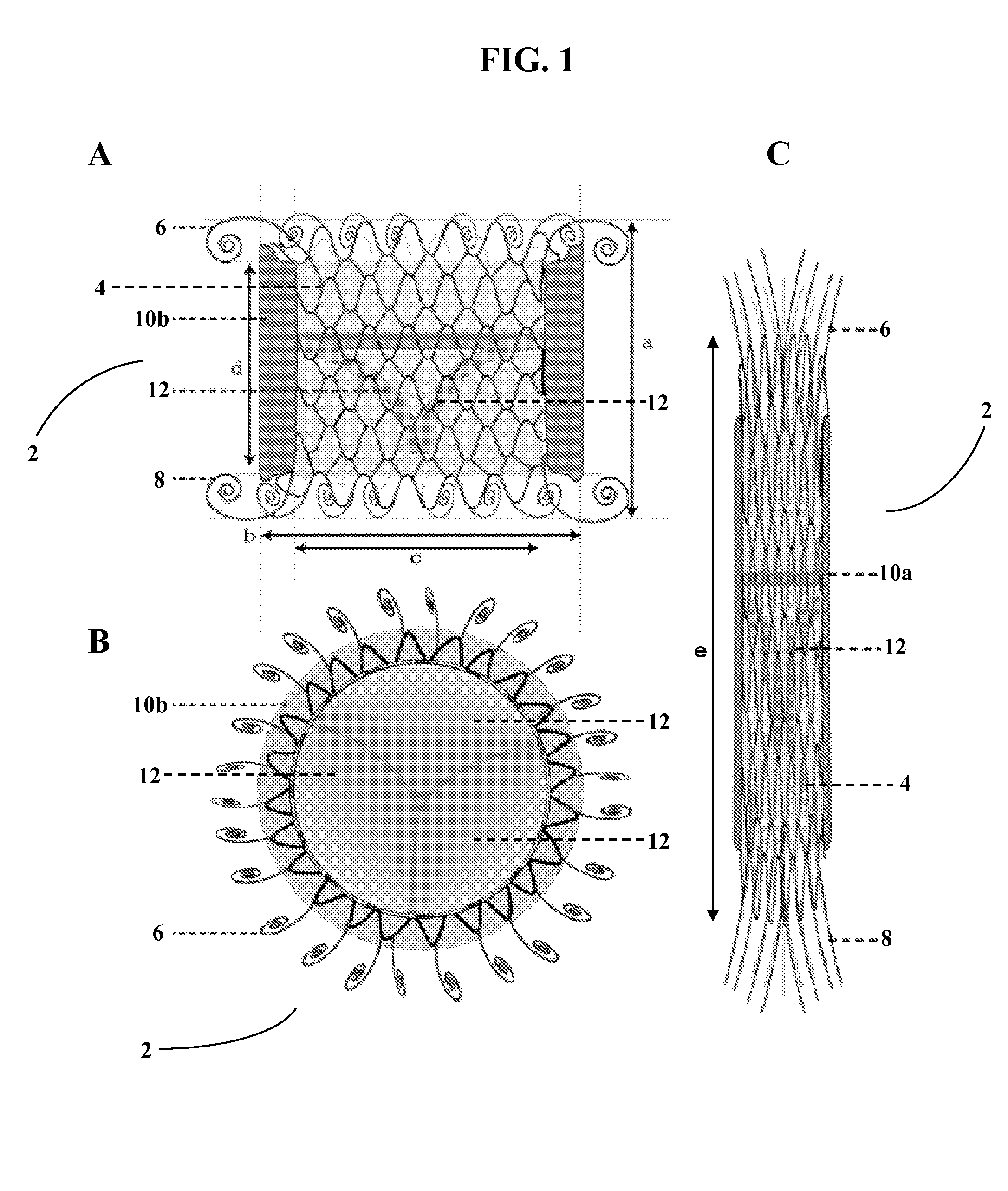
[0030]In one aspect, valve prostheses are provided comprising a self-expanding stent comprising an outer surface, an interior surface, a middle region, an upper anchoring flange, and a lower anchoring flange, wherein the stent has an unexpanded and an expanded state; a cuff comprising an absorbent material disposed at least partially circumferentially around the outer surface of the stent, wherein the absorbent material expands by absorption of a fluid to substantially adhere the prosthesis at an implantation site, and wherein the anchoring is delayed for a time sufficient to permit positioning of the prosthesis at the implantation site; and a valve comprising at least two leaflets fixedly attached to the interior surface of the stent. In preferred embodiments, the prost...

embodiment ii

General Embodiment II

[0052]The following description pertains to a second general embodiment of the present disclosure, which pertains to inventive valve prostheses; methods for replacing a damaged or diseased valve; systems for delivering a valve prosthesis; kits; and, methods for delivering a valve prosthesis.

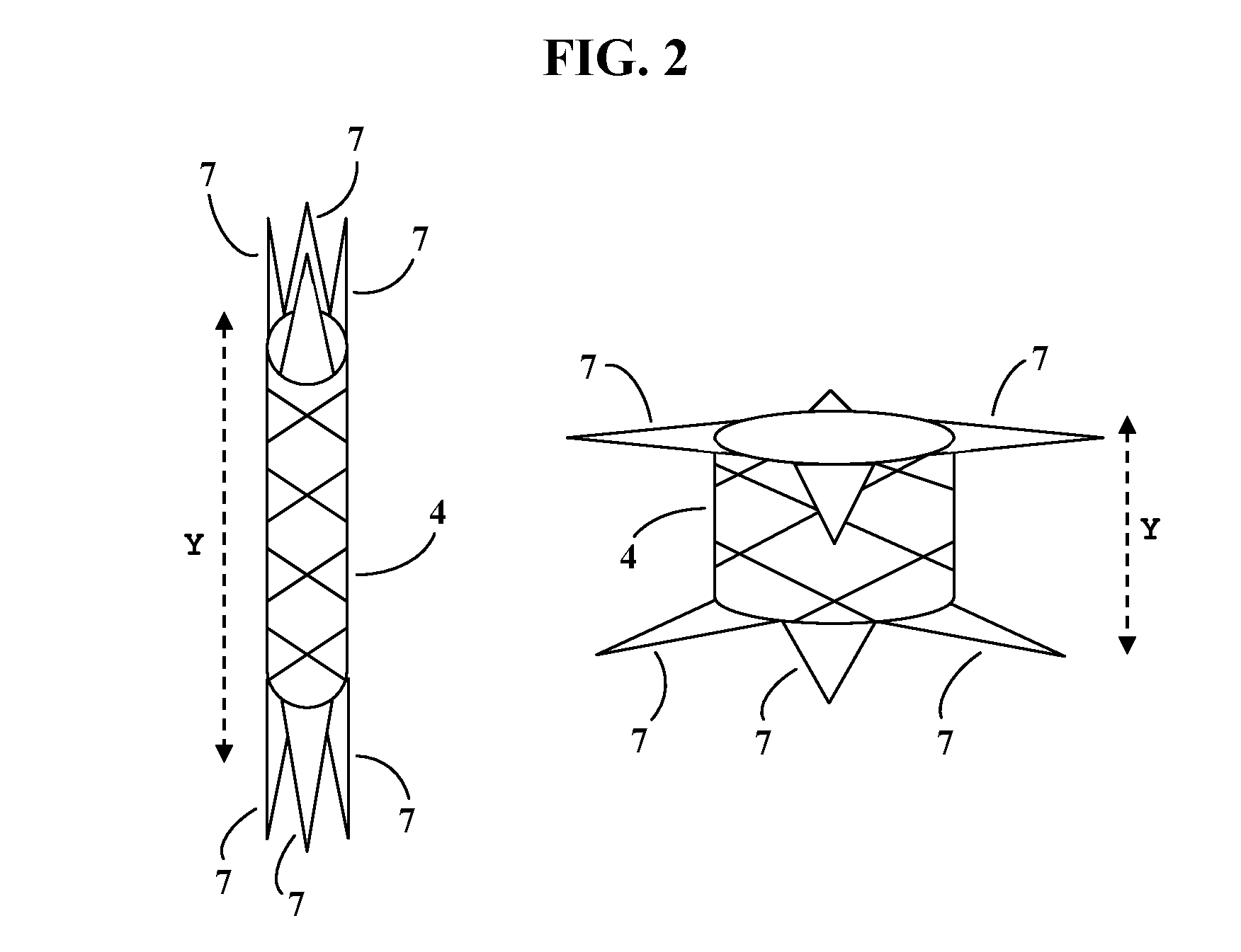
[0053]In one aspect, provided are valve prostheses comprising an at least partially self-expanding stent comprising a wire framework defining outer and interior surfaces, and upper and lower anchoring flanges interposed by a middle region, the stent having an unexpanded and an expanded state, and the lower anchoring flange having at least one geometric dimension that is greater than the corresponding dimension of the upper anchoring flange; and a valve comprising at least one leaflet fixedly attached to the interior surface of the stent.

[0054]The stent may be configured to be at least partially self-expanding. For example, the stent may be capable of self-expanding to its sta...

example 1

Percutaneous Implantation Via Transfemoral Approach

[0113]An exemplary delivery and implantation procedure may be performed as follows using the presently disclosed system for delivering a valve prosthesis, as well as a valve prosthesis according to the present disclosure.

[0114]First, the femoral vein (right or left) is accessed and a vascular sheath is inserted using the seldinger technique. The atrial septum is crossed via standard transseptal technique, and an atrial hole is created / enlarged via balloon dilation septostomy (10-15 mm angioplasty balloon)

[0115]A super-stiff guidewire is carefully shaped to and then positioned in the left ventricle through the newly created atrial hole. The femoral venous access site is made larger or “dilated up” with sequentially larger vascular dilators sized appropriately to match the diameter of the delivery system.

[0116]The valve prosthesis is compressed and positioned on the dock of the delivery system, and the system is otherwise prepared for...


PUM

PropertyMeasurementUnit
thicknessaaaaaaaaaa
diameteraaaaaaaaaa
diameteraaaaaaaaaa

Abstract

The present disclosure relates to valve replacement devices that are foldable for catheter-based deployment to the site of implantation, as well as systems for the delivery of valve prostheses, including prostheses having the special characteristics of the disclosed valve replacement devices. The devices include highly effective adhering mechanisms for secure and enduring precision implantation. The adhering mechanisms may employ a unique sealing mechanism that includes a cuff that expands slowly whereby the device is not secured in place until the completion of the implantation procedure. The implanted device, optionally together with the cuff, prevents perivalvular leaks and incorporate an appropriate leaflet system for reliable functioning in situ.

Description

CROSS-REFERENCE TO RELATED APPLICATION[0001]The present application claims priority to U.S. Provisional Application No. 61 / 241,659, filed Nov. 5, 2009, which is hereby incorporated by reference in its entirety.TECHNICAL FIELD[0002]The present disclosure relates to anatomical valve replacement devices and methods and systems for replacing a valve and for delivering a stented device.BACKGROUND[0003]The mitral valve is a complex structure whose competence relies on the precise interaction of annulus, leaflets, chordae, papillary muscles and left ventricle (LV). Pathologic changes in any of these structures can lead to valvular insufficiency. Myxomatous leaflet / chordal degeneration, and dilated ischemic cardiomyopathy secondary to chronic post infarction ventricular remodeling are among most common mechanisms producing mitral regurgitation (MR). These two disease processes account for about 78% of all cases of MR treated surgically.[0004]As part of the Framingham Heart Study, the preval...

Claims


Application Information

Patent Timeline
Patent Type & Authority Applications(United States)
IPC IPC(8): A61F2/24A61F2/84
CPCA61F2/2418A61F2/2436A61F2210/0061A61F2220/0008A61F2230/0078A61F2250/0069A61F2230/0054A61F2230/0058A61F2250/0039A61F2/24A61F2/2409A61F2210/0076A61F2250/003A61F2210/0004A61F2210/0014
Inventor GORMAN, III, JOSEPH H.GORMAN, ROBERT C.GILLESPIE, MATTHEW J.
Owner THE TRUSTEES OF THE UNIV OF PENNSYLVANIA
Why Eureka
Try Eureka