
System and method for concurrent operation of dual interfaces between uicc and mobile device

a dual interface and mobile device technology, applied in the field of system and method for concurrent operation of dual interfaces between uicc and mobile devices, can solve the problems of high implementation cost of communication processors, complex design changes, and complex operation, and achieve the effect of reducing design changes and reducing manufacturing costs

Inactive Publication Date: 2011-10-13
SUN JUN +1
View PDF10 Cites 18 Cited by
  • Summary
  • Abstract
  • Description
  • Claims
  • Application Information

AI Technical Summary

Benefits of technology

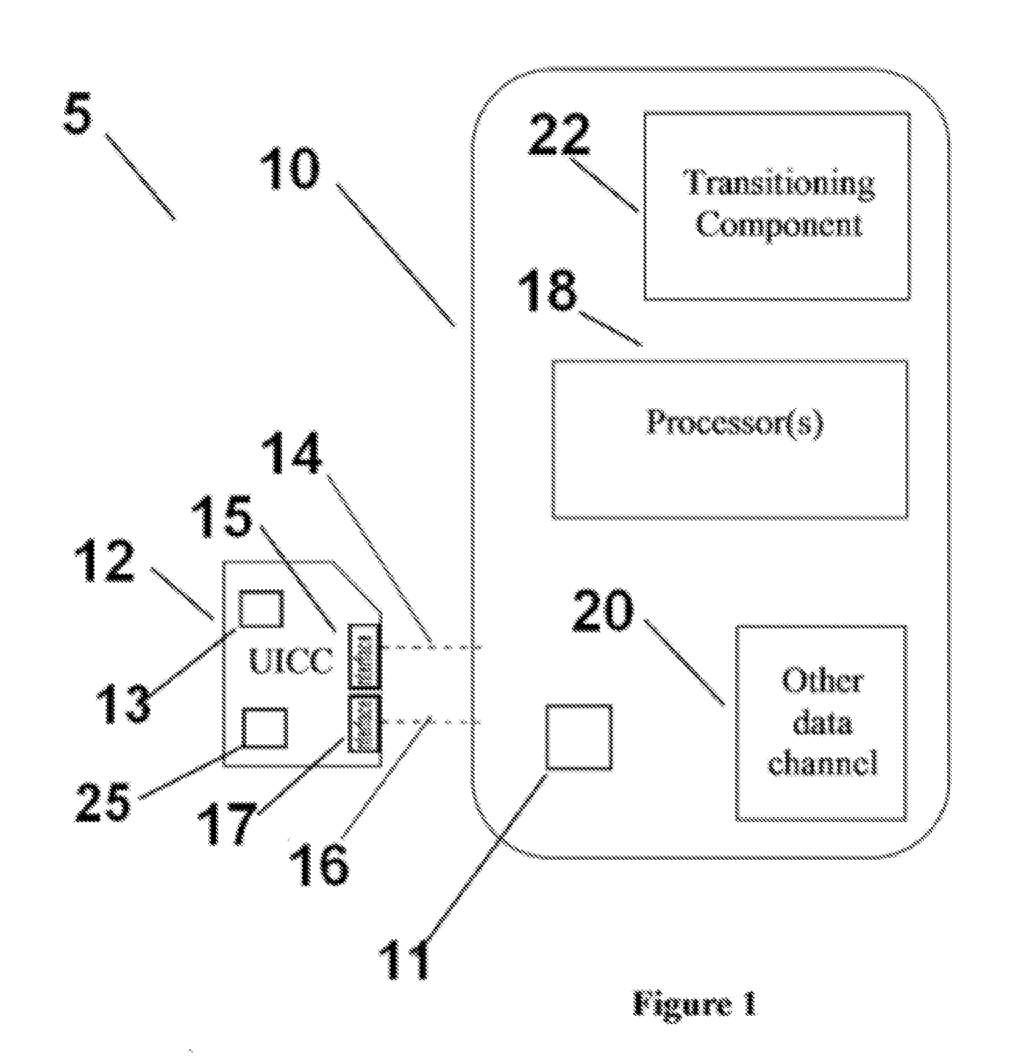
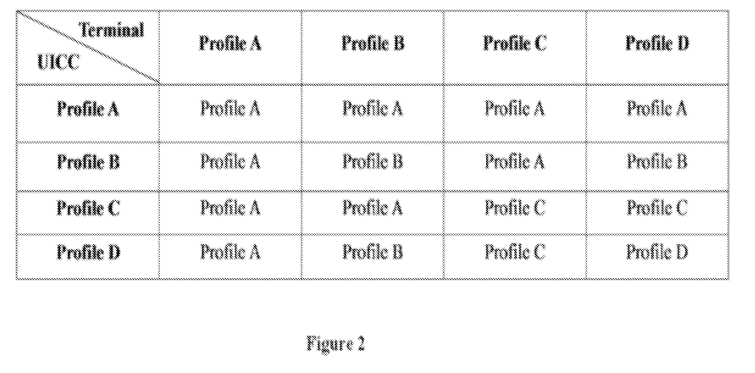
[0012]This invention relates to 1) a new operation mode, called Concurrent mode that supports two interfaces between the terminal and the UICC to be used at the same time. One of the interfaces is the legacy ISO interface that supports SIM applications, and the other interface is the IC-USB interface that supports higher speed data transfer; 2) two new capability profiles for both terminals and UICCs as a result of this new Concurrent operation mode. A capability profile here refers to the set of operational modes a terminal or a UICC supports, plus the logic for transitioning among these operation modes during run-time. The two new profiles supported by this invention include one that includes ISO and Concurrent modes of operation, and the other that includes ISO, IC-USB, and Concurrent modes of operation; 3) process for making terminals and UICCs having one of the two new capability profiles compatible with those with standard capabilities profiles; and 4) a low cost implementation of the Concurrent mode where a UICC card is connected through the ISO 7816 interface to the communication processor of the terminal and connected through the IC-USB interface to the application processor of the terminal with a USB bridge chip, and where the UICC can be configured as either a USB host or a USB gadget.
[0018]In one embodiment, a terminal contains a communication processor and an application processor. The communication processor is linked to and controls the ISO 7816 interface of the UICC, while the application processor is linked to and controls the IC-USB interface. When the system operates in the Concurrent mode, all APDU commands are sent to the ISO 7816 interface through the communication processor, which is the same as the today's phone architecture. Meanwhile all other protocol commands (such as those used for mass storage and networking) are sent to the IC-USB interface through the application processor, enabling advanced services to mobile applications without burdening the Communication Processor.
[0020]In a further embodiment, to reduce design changes and lower manufacturing cost by reusing an existing phone's design, a USB bridge chip is used to connect the IC-USB interface of UICC with the existing USB gadget port on the application processor.

Problems solved by technology

Several potential issues may arise when implementing a UICC system conforming to the ESTI TS 102 600 standard.
This poses implementation challenges to terminals that have separate communication and application processors (such as most smart phones).
This conflicts with the current architecture of mobile handsets and would require extensive changes in both side as well as the interface changes between application processor and communication processor.
This incurs high implementation cost to communication processor and again introduces interface changes between application processor and communication processor.
Today, application processor and communication processor are two different segments of the industry, and thus making this cross-segment interface change requires extraordinary amount of effort.
While demands for IC-USB based advanced services mentioned above are already here today, there is no IC-USB chipset available on the market today.
Because of the above mentioned difficulty, such IC-USB chipset may not be available on the market for a while.

Method used


Image

  • System and method for concurrent operation of dual interfaces between uicc and mobile device
  • System and method for concurrent operation of dual interfaces between uicc and mobile device
  • System and method for concurrent operation of dual interfaces between uicc and mobile device

Examples


Embodiment Construction

[0031]The present invention will now be described more fully hereinafter with reference to the accompanying drawings, in which preferred embodiments of the invention are shown. This invention may, however, be embodied in many different forms and should not be construed as limited to the embodiments set forth herein. Rather, these embodiments are provided so that this disclosure will be thorough and complete, and will fully convey the scope of the invention to those skilled in the art. Like numbers refer to like elements throughout.

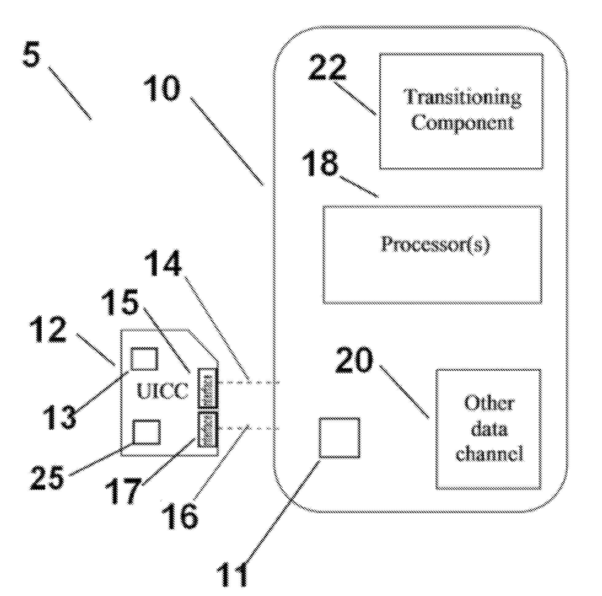
[0032]FIG. 1 describes a system 5 in accordance with one embodiment of the present invention. The system 5 includes a terminal 10 and a UICC 12. The UICC 12 has an ISO 7816 interface 15 with corresponding channel 14 that connects to the terminal 10 and an optional IC-USB 17 interface with corresponding channel 16 that connects to the terminal 10. The computer system 5 includes a first interface 15 and second interface 17, computer memories 11, 13 for stori...


PUM


Abstract

This invention relates to a process and system for operating a UICC with a terminal such as a cell phones or a PC, where there is an ISO 7816 channel and / or an IC-USB channel between the UICC and the terminal. The invention enables a Concurrent operation mode for simultaneously communicating data or ISO protocol commands over the ISO 7816 channel and communicating data or USB protocols over the IC-USB channel. The system dynamically enters and exits Concurrent mode when both the UICC and the terminal support it, and operates in standard operation modes when either of them does not support it. In one embodiment, on the terminal, the ISO interface is connected to the communication processor and the IC-USB interface is connected to the application processor through a USB bridge chip, and the UICC can be configured either as a host or a gadget.

Description

FIELD OF THE INVENTION[0001]The present invention relates to systems with a terminal and a Universal Integrated Circuit Card (UICC), and the concurrent operation of dual interfaces between the terminal and the UICC.BACKGROUND OF THE INVENTION[0002]Smart cards (SC) are widely used today in applications such as healthcare, public phone, parking, loyalty programs, cash payments, credit payments and portable data storage. The SC is essentially a small form-factor card with embedded integrated circuit, which may include a memory for storing data and instructions, and a microprocessor for executing the instructions. The SC functions in conjunction with a SC reader which is attached to a computing or communication device, such as a personal computer, a cell phone, or a point of sale terminal (henceforth all referred to as terminal). The SC communicates with the SC reader using a serial protocol. The specification of the protocol was originally published by the International Standard Organi...

Claims


Application Information

Patent Timeline
IPC IPC(8): G06F13/14G06K19/07
CPCG06K19/07733G06K19/07
Inventor SUN, JUNWEI, YUJI
Owner SUN JUN
Learn More