Remotely-triggered submerged launch canisters

a submerged launch and remote trigger technology, applied in the field of underwater deployment systems, can solve the problems of inability to fully autonomously operate an underwater vehicle, lack of a straightforward, rugged and reliable means, and inability to operate autonomously for a long time, etc., to achieve the effect of maximizing the post-deployment operational lifespan of an underwater vehicle, simple operation, and low cos

Inactive Publication Date: 2011-10-20
RAYTHEON CO
View PDF4 Cites 5 Cited by
  • Summary
  • Abstract
  • Description
  • Claims
  • Application Information

AI Technical Summary

Benefits of technology

[0004]In view of the foregoing section entitled “Background,” there exists an ongoing need to provide embodiments of a deployment device that can be utilized to reliably deploy an Unmanned Underwater Vehicle (or other waterborne object) or to pre-position an Unmanned Underwater Vehicle on the seafloor for deployment at a later juncture. In the latter regard, it is particularly desirable to provide a deployment device that enables an Unmanned Underwater Vehicle to be pre-positioned at a desired location of deployment and to be remotely activated at a subsequently-determined time to maximize the post-deployment operational lifespan of the Unmanned Underwater Vehicle. It is also generally desirable for such a deployment device to be cost-effective, scalable, handsafe, rugged, and relatively straightforward to operate to facilitate usage by in-field military personnel, including divers operating in potentially adverse maritime conditions (e.g., low ambient light, Sea States approaching or exceeding Code 3, etc.). Other desirable features and characteristics of the present invention will become apparent from the subsequent Detailed Description and the appended Claims, taken in conjunction with the accompanying Drawings and Background.

Problems solved by technology

Widespread in-field usage of UUVs has, however, been somewhat hindered by the lack of a straightforward, rugged, and reliable means that can be utilized by non-technical military personnel to deploy Unmanned Underwater Vehicles on an ad hoc, as-needed basis.
In addition, the duration of time over which an Unmanned Underwater Vehicle can operate autonomously is inherently limited by the capacity of the battery or batteries deployed aboard the UUV.
It is generally not practical for an Unmanned Underwater Vehicle to remain dormant and exposed on the seafloor for a prolonged period of time prior to activation.
Unmanned Underwater Vehicles are thus subject to timing constraints that may deter or prevent UUV deployment when the time frame for accomplishment of mission objectives is uncertain or relatively lengthy; e.g., several days or weeks post-deployment.

Method used


Image

  • Remotely-triggered submerged launch canisters
  • Remotely-triggered submerged launch canisters
  • Remotely-triggered submerged launch canisters

Examples


Embodiment Construction

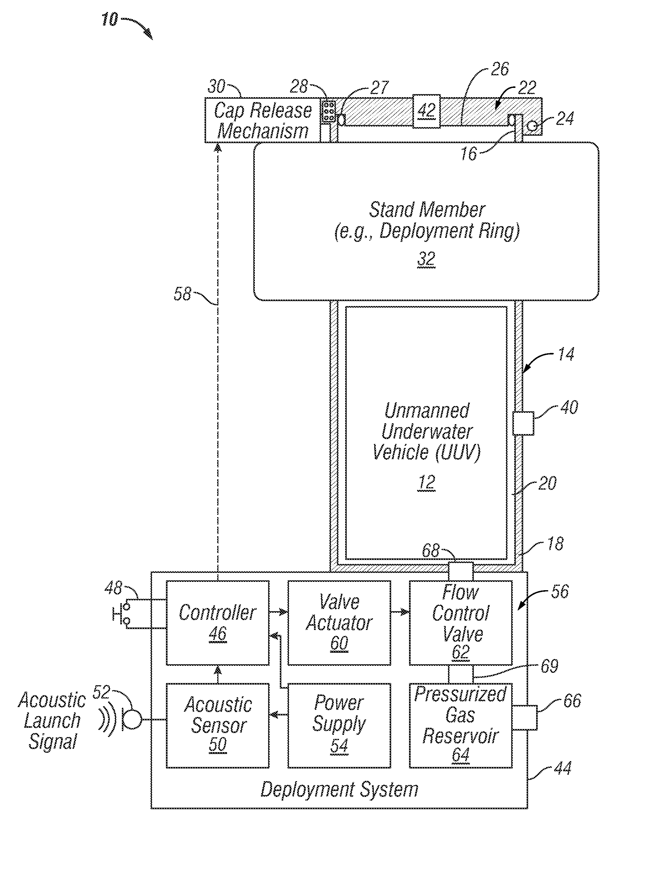
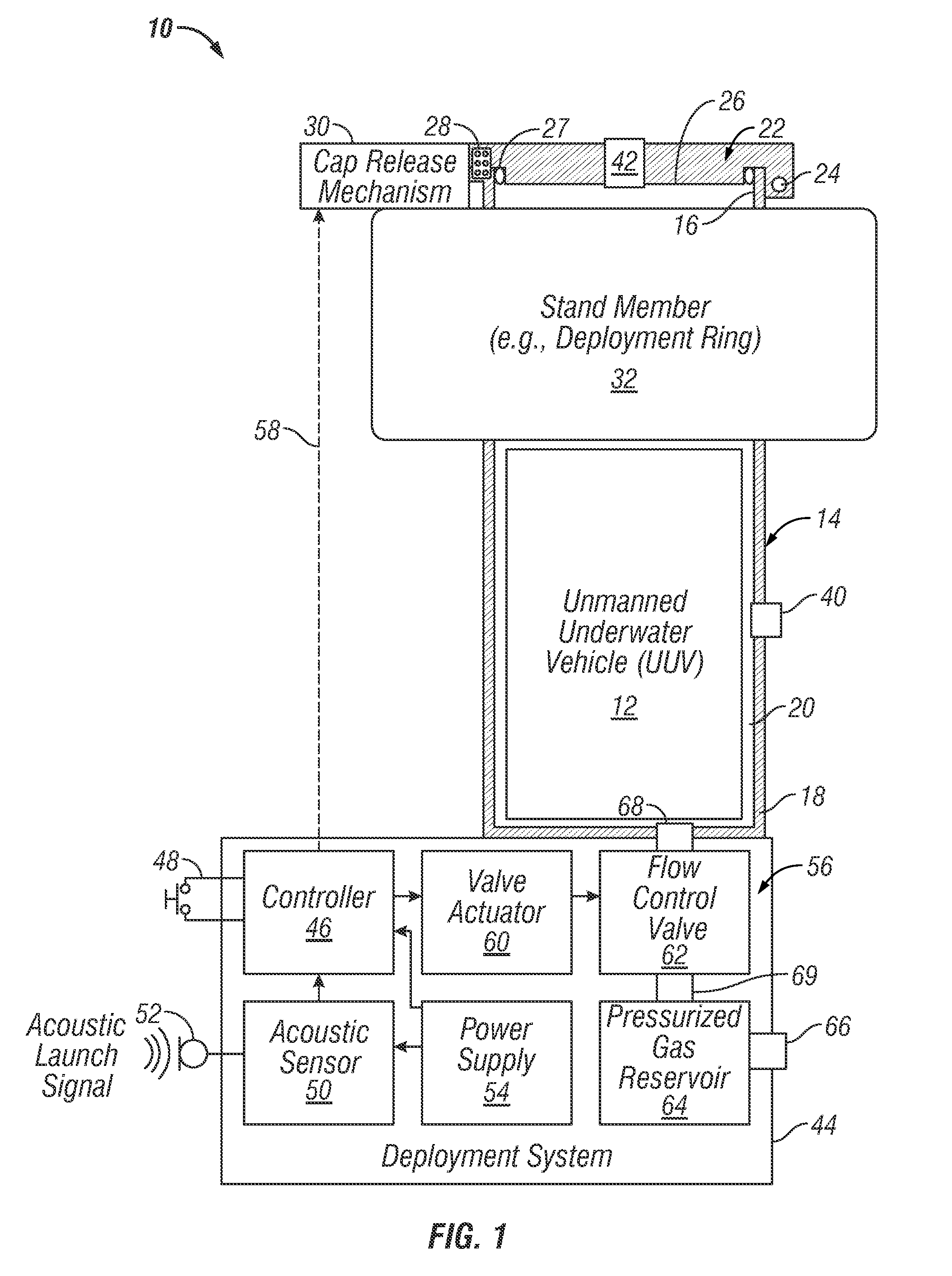
[0010]The following Detailed Description is merely exemplary in nature and is not intended to limit the invention or the application and uses of the invention. To the contrary, many embodiments of the submerged launch canister and the like are not limited by the drawings or other representations contained herein, but rather encompass a wide range of equivalent embodiments that incorporate the general concepts set-forth in this document and its attachments. The term “canister” as appearing herein is defined broadly to include any sealable container, regardless of shape, size, structural features, material composition, etc., suitable for the underwater transport and deployment of an Unmanned Underwater Vehicle or other waterborne object as described more fully below. As further appearing herein, the term “seafloor” is utilized to denote any submerged surface that may support the submerged launch canister as further described below.

[0011]FIG. 1 is a functional block diagram of a Submer...


PUM


Abstract

Embodiments of a submerged launch canister are provided for the remotely-initiated deployment of a waterborne object. In one embodiment, the submerged launch canister includes a pressure vessel and a remotely-triggered deployment system. The pressure vessel has an open end portion and a storage cavity configured to receive the waterborne object therein. The remotely-triggered deployment system is configured to propel the waterborne object from the storage cavity, through the open end portion, and into a body of water when remotely triggered.

Description

CROSS REFERENCE TO RELATED APPLICATION[0001]This application claims priority to U.S. Provisional Application Ser. No. 61 / 325,712, filed Apr. 19, 2010, the entire contents of which are hereby incorporated by reference.TECHNICAL FIELD[0002]The following disclosure relates generally to underwater deployment systems and, more specifically, to submerged launch canisters utilized to remotely deploy Unmanned Underwater Vehicles and other waterborne objects.BACKGROUND[0003]Unmanned Underwater Vehicles (also commonly referred to as “Autonomous Underwater Vehicles”) are utilized for various purposes in military and civilian contexts. In the military context, Unmanned Underwater Vehicles (“UUVs”) may be employed to perform oceanic and littoral surveillance or to detect, and possibly disable, naval mines or other threats. Widespread in-field usage of UUVs has, however, been somewhat hindered by the lack of a straightforward, rugged, and reliable means that can be utilized by non-technical milit...

Claims


Application Information

Patent Timeline
Patent Type & Authority Applications(United States)
IPC IPC(8): B63G8/00
CPCF41F3/10F41F3/07
Inventor BOSSERT, DAVID E.ZERBE, JEFFREY N.SAMPSON, RAY
Owner RAYTHEON CO
Why Eureka
Try Eureka