Balloon Tying Apparatus and Method

a balloon and tying technology, applied in the field of balloon tying apparatus and method, can solve the problems of difficult and sometimes difficult tying of balloons, and achieve the effects of convenient and convenient convenient and convenient storage and retrieval, and convenient and fast blowing up of balloons

Active Publication Date: 2011-10-20
DELLAQUILA PETER JAMES
View PDF2 Cites 15 Cited by
  • Summary
  • Abstract
  • Description
  • Claims
  • Application Information

AI Technical Summary

Benefits of technology

[0025](d) with the use of a combination balloon pump and tying tool, the user does not have to put the balloon pump down in order to tie a balloon.
[0026]This makes the process of preparing blown up balloons significantly more efficient and faster.
[0027]Accordingly, the present invention provides that the balloon pump with device built into handle to aid in the tying of balloons can be used to bl

Problems solved by technology

The tying of inflated balloons is sometimes met with great difficulty.
Additionally, per

Method used


Image

  • Balloon Tying Apparatus and Method
  • Balloon Tying Apparatus and Method
  • Balloon Tying Apparatus and Method

Examples


Embodiment Construction

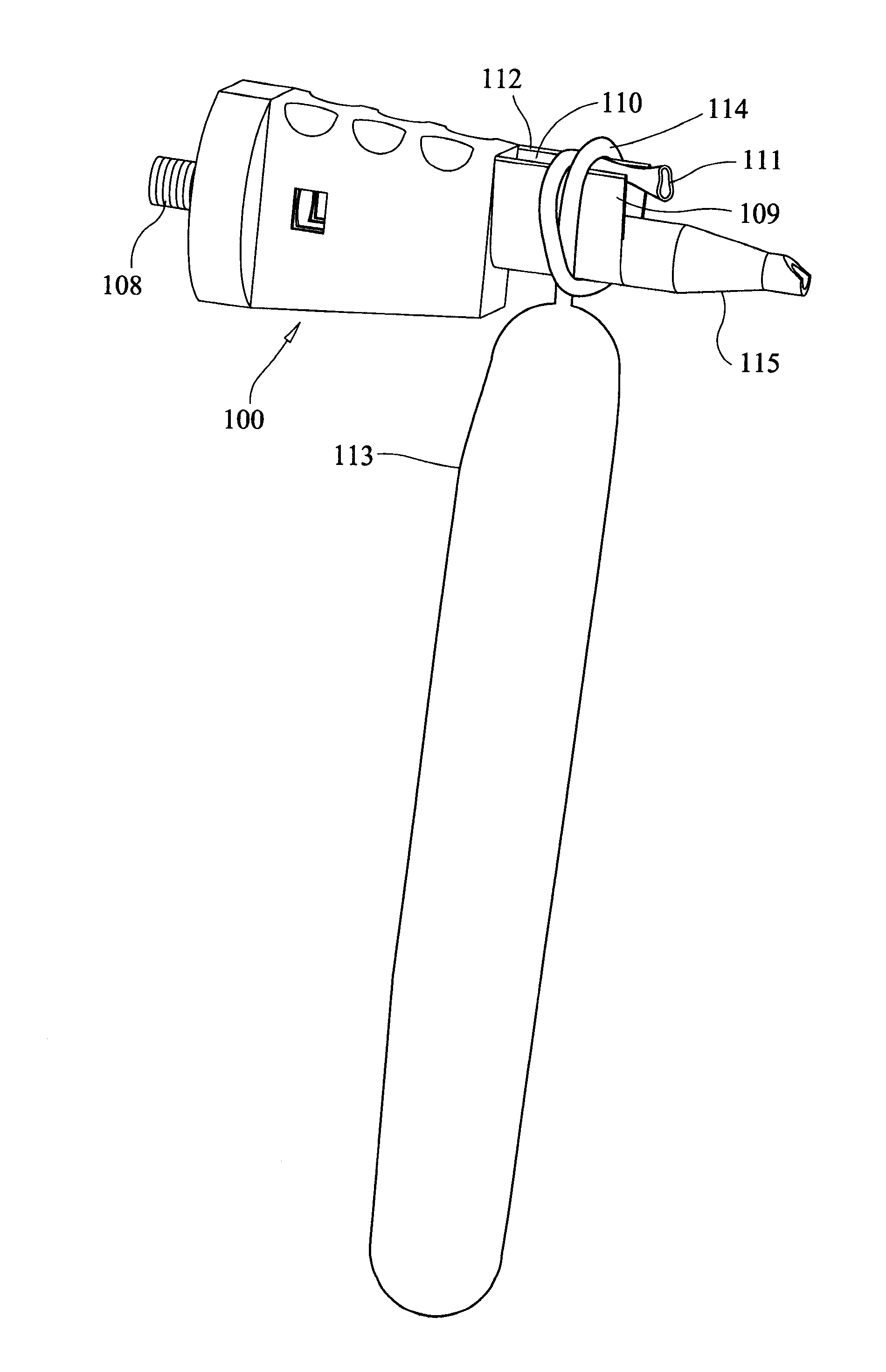
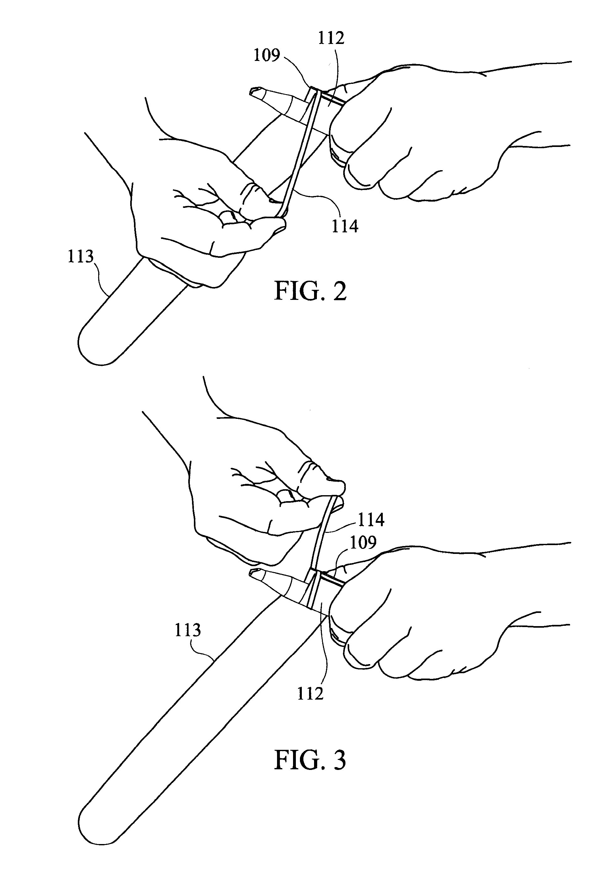
[0038]Gas dispenser 100 has an inlet 108 and an outlet 115. Gas dispenser 100 is any dispenser suitable for providing gas to fill a balloon. The gas supplied is any acceptable balloon filing gas which may include, but would not be limited to, ambient air, helium, combinations thereof, and the like. Gas dispenser 100 may be attached to a manual hand operated inflating device, a compressed gas tank, a mechanical pump, or the like. Inlet 108 is connected either by hose, or direct connection to a gas source (not shown). Gas passes through the interior of dispenser 100, wherein the interior is constructed and arranged to receive gas through inlet 108 and direct the gas through outlet 115. Incorporated with dispenser 100 is a structure constructed and arranged to facilitate the tying of an inflated balloon. The structure is formed of a first wall 109 and a second wall 112 positioned above outlet 115 such that the upper surface of outlet 115 and each of first wall 109 and a second wall 112...


PUM


Abstract

A balloon tying article is provided with a first wall, a second wall and a cavity therebetween whereby a balloon is tied using each of the walls to knot the balloon neck

Description

INDEX TO RELATED APPLICATIONS[0001]This application claims benefit from U.S. Provisional Patent No. 61 / 325,284, filed Apr. 17, 2010, the disclosure of which is incorporated herein by reference in its entirety.BACKGROUND OF THE INVENTION[0002]The tying of inflated balloons is sometimes met with great difficulty. Many people are unable to form a knot in the inflating neck of an inflated balloon. Additionally, persons inflating and tying many balloons find it more difficult as more balloons are tied. A need exists for an effective balloon tying article.BRIEF SUMMARY OF THE INVENTION[0003]The present invention provides an article incorporated with a balloon inflating nozzle that facilitated tying inflated balloons.[0004]The present invention is an article for tying a balloon comprising:[0005]a first wall;[0006]a second wall;[0007]each of said first and second wall positioned above a balloon inflating nozzle; and[0008]a cavity defined by each of said first wall, second wall and nozzle.[0...

Claims


Application Information

Patent Timeline
IPC IPC(8): B65B3/04
CPCA63H27/10B65B23/02A63H2027/1083A63H2027/105
Inventor DELLAQUILA, PETER
Owner DELLAQUILA PETER JAMES
Why Eureka
Try Eureka