Eureka AIR delivers breakthrough ideas for toughest innovation challenges, trusted by R&D personnel around the world.

Autostereoscopic display device

a display device and autostereoscopic technology, applied in optics, instruments, electrical devices, etc., can solve the problem of separation of the view projected by the lenticular sheet by dark zones, and achieve the effect of reducing the intensity modulation depth

Inactive Publication Date: 2011-10-20
KONINKLIJKE PHILIPS ELECTRONICS NV
View PDF5 Cites 10 Cited by
  • Summary
  • Abstract
  • Description
  • Claims
  • Application Information

AI Technical Summary

Benefits of technology

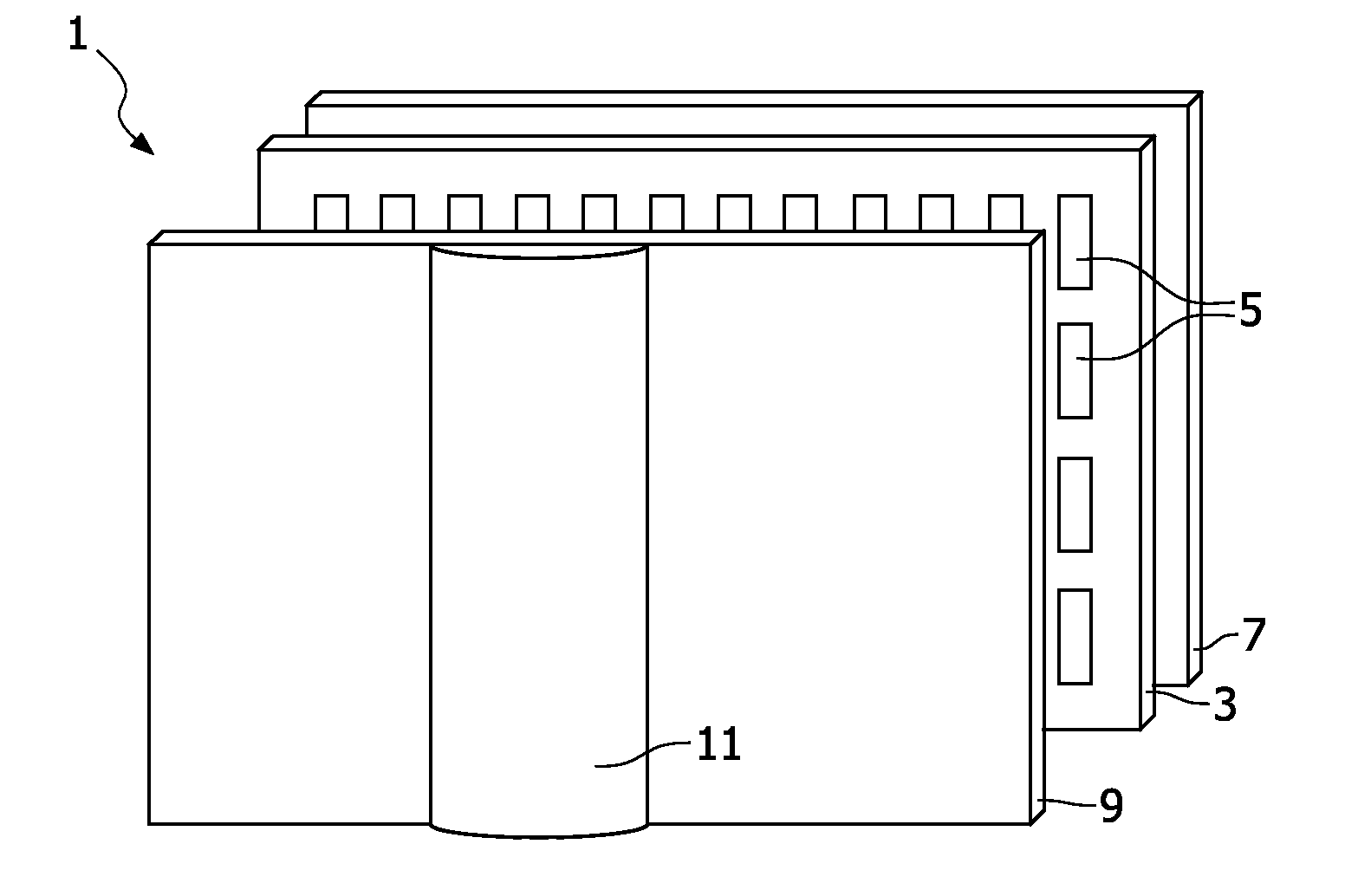
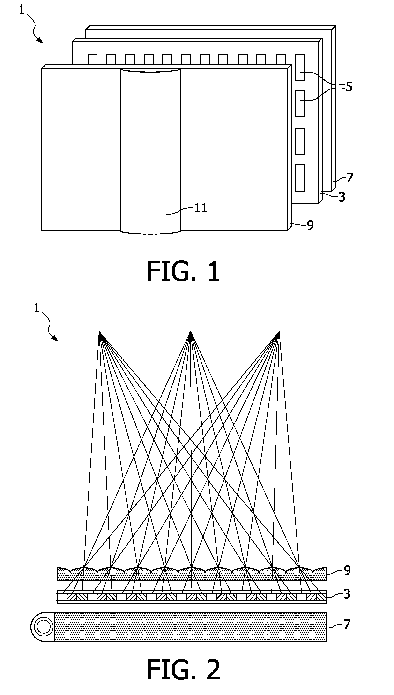
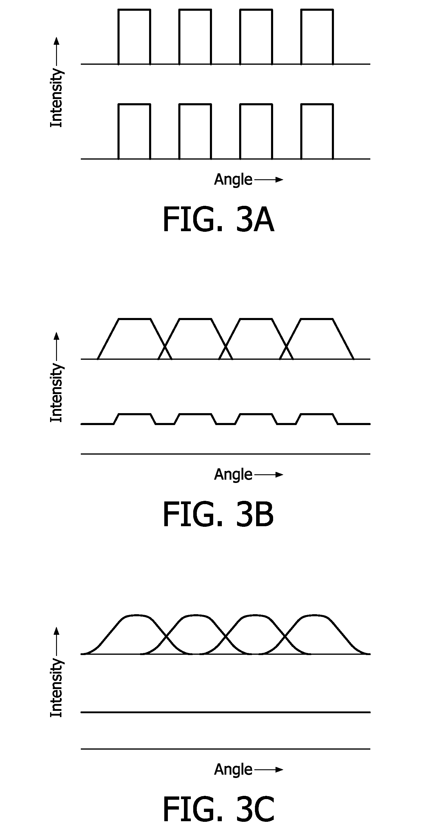
[0010]wherein the geometry of the view forming elements defines a substantially periodic inter-element variation in the width direction of the display device, for reducing brightness non-uniformities in the views.
[0037]According to this aspect of the invention, brightness non-uniformities are reduced, for example, by varying the location, width and / or spacing of the display pixels arranged in registration with the view forming module. In a specific embodiment, display pixels underlying “odd” and “even” view forming elements are shifted slightly to the left and right, respectively, as compared to their positions in a regular array of display pixels.

Problems solved by technology

However, a problem associated with the device is that the views projected by the lenticular sheet are separated by dark zones caused by “imaging” of the non-emitting black matrix which typically defines the display pixel array.

Method used


Image

  • Autostereoscopic display device
  • Autostereoscopic display device
  • Autostereoscopic display device

Examples


Embodiment Construction

[0053]The invention provides an autostereoscopic display device of the type that has an image forming means and a view forming module. The autostereoscopic device may be a multi view display, giving a look around impression of image objects. The image forming means may be any image forming means envisaged that is suitable for display of an image. Preferably the way in which output of the pixels is provided by the image forming means does not require illumination of the pixels through the view forming module. Preferably the image forming means is an active image forming means such as an electrical display device where the pixels provide output without external input. Such means include but are not limited to cathode ray tubes, plasma display panels, liquid crystal displays or light emitting diode displays. In these cases, the output of the display pixels is not dependent on external illumination. The device may also have a driving means arranged to drive the image forming means with ...


PUM


Abstract

There is disclosed a multi-view autostereoscopic display device comprising an image forming means arranged over and in registration with a view forming module. The image forming means has a planar array of light emissive display pixels arranged in rows and columns for producing a display, the display pixels being spatially defined by an opaque matrix. The image forming means may, for example, be a LCD display panel. The view forming module is configurable to function as a plurality of view forming elements arranged in the width direction of the display device, each view forming element focusing the light output from an adjacent group of the display pixels into a plurality of views for projection towards a user in respective different directions. The view forming module may, for example, be an array of lenticular lenses. The geometry of the view forming elements defines a substantially periodic inter-element variation in the width direction of the display device, for reducing brightness non-uniformities in the views. The inter-element variation may, for example, be provided by varying at least one of the widths, the focusing powers and the relative positions of the geometric axes of the lenticular lenses in the width direction of the display device.

Description

FIELD OF THE INVENTION[0001]This invention relates to an autostereoscopic display device comprising an image forming means, such as a display panel having an array of display pixels, and a view forming module. The view forming module is, or is configurable to function as, an array of view forming elements arranged over the image forming means and through which the display pixels are viewed. The invention also relates to an autostereoscopic imaging method.BACKGROUND OF THE INVENTION[0002]A known autostereoscopic display device is described in GB 2196166 A. This known device comprises a two dimensional emissive liquid crystal display panel having a row and column array of display pixels acting as an image forming means to produce a display. An array of elongate lenticular lenses extending parallel to one another overlies the display pixel array and acts as a view forming means. Outputs from the display pixels are projected through these lenticular lenses, which lenses function to modi...

Claims


Application Information

Patent Timeline
Patent Type & Authority Applications(United States)
IPC IPC(8): G02B27/22G02B30/29G02B30/30
CPCG02B27/2214H04N13/0415H04N13/0404H04N13/305H04N13/317G02B30/30G02B30/29G02B3/00H04N13/00G02B30/27
Inventor MICHAEL KRIJN, MARCELLINUS PETRUS CAROLUSDE ZWART, SIEBE TJERKBERRETTY, ROBERT-PAUL MARIOVAN DER HORST, JANBARENBRUG, BART GERARD BERNARD
Owner KONINKLIJKE PHILIPS ELECTRONICS NV
Why Eureka
Eureka Blog
Learn More