Image forming apparatus and image forming method

a technology of image forming apparatus and forming method, which is applied in the direction of electrographic process apparatus, instruments, optics, etc., can solve the problems of affecting the accuracy of image forming method, so as to achieve precise manner, detect the effect of toner supply, and avoid erroneous detection

Active Publication Date: 2011-10-20
SHARP KK
View PDF7 Cites 10 Cited by
  • Summary
  • Abstract
  • Description
  • Claims
  • Application Information

AI Technical Summary

Benefits of technology

[0038]According to the fourth aspect of the present invention, the effect of toner supply can be detected with precision. Specifically, since the pressure on the developer becomes maximum at the bottom of the first conveying passage, voids are unlikely to form inside the developer. Accordingly it is possible to precisely detect the effect of toner supply with the toner supply detecting sensor.
[0039]According to the fifth aspect of the present invention, since the force of agitating the developer in the rotational direction of the first conveying member can be enhanced so that floating toner, or the supplied toner being conveyed floating over the developer, is unlikely to occur, it is possible for the toner supply detecting sensor to precisely detect the effect of toner supply.
[0040]According to the sixth aspect of the present invention, since it is possible to perform toner supply in a more exact manner compared to toner concentration control based on the toner concentration detected by the toner concentration detecting sensor, it is possible to perform toner concentration control and detection of toner empty, in a more precise manner.
[0041]Further, since the average value of the output from the toner supply detecting sensor over, for example one cycle of the helical blade is sampled for a fixed period of time immediately after the start of the supplying operation of the toner supply device, and the difference between the maximum and minimum values is calculated, it is possible to obtain a correct difference between the toner supply sensor outputs before and after a toner supply when the toner concentration controller performs control so as to continue the permitted period of toner supply operation until the output from the paper conveyance detecting sensor located at a certain position in the paper conveyance path indicates the passage of the last printing paper being conveyed. As a result it is possible to determine the status of toner empty without erroneous detection.
[0042]According to the seventh aspect of the present invention, since it is possible to perform sampling for toner supply detection at the best timing, it is possible to correctly detect the status of toner empty without erroneous detection when the toner of the toner supply device has been used up. As a result, it is possible to prevent occurrence of carrier adherence resulting from reduction in toner concentration.
[0043]According to the eighth aspect of the present invention, since toner empty can be precisely detected without making erroneous detection, it is possible to prevent occurrence of carrier adherence resulting from reduction in toner concentration, hence realize highly qualified image printout.

Problems solved by technology

However, in the technology described in Patent Document 1, in the case where no toner is supplied even after a toner supply command was given to the toner cartridge because of toner empty in the toner cartridge, if the toner concentration detecting sensor is located away from the toner supply port through which toner is supplied, detection of toner empty is delayed because the fall of toner concentration detected by the toner concentration detecting sensor is sluggish.
As a result, there occurs the problem that the occurrence of carrier adherence becomes more frequent.

Method used


Image

  • Image forming apparatus and image forming method
  • Image forming apparatus and image forming method
  • Image forming apparatus and image forming method

Examples


Embodiment Construction

[0059]Now, the embodied mode for carrying out the present invention will be described with reference to the drawings.

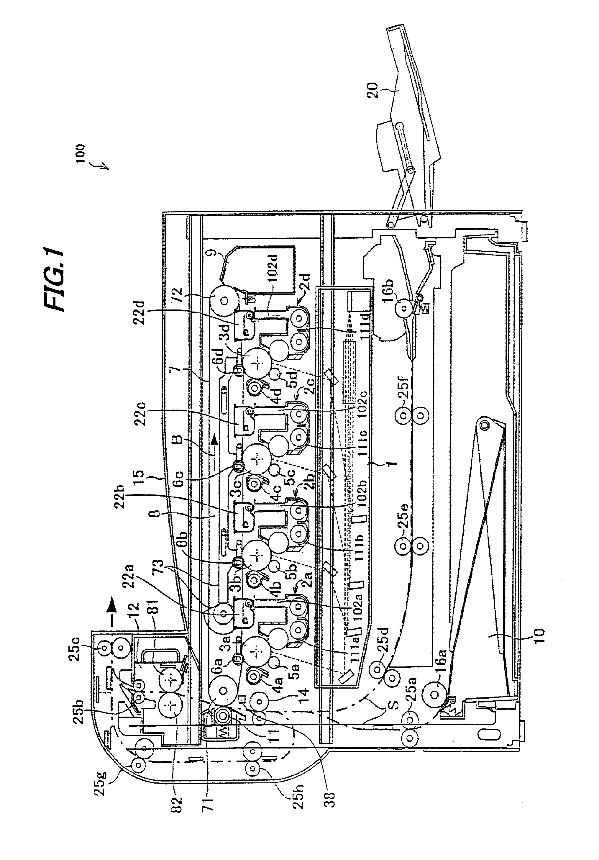
[0060]FIG. 1 shows one exemplary embodiment of the present invention, and is an illustrative view showing the overall configuration of an image forming apparatus 100 according to the embodiment of the present invention.

[0061]Image forming apparatus 100 of the present embodiment forms an image with toners based on electrophotography, including: as shown in FIG. 1, photoreceptor drums 3a, 3b, 3c and 3d (which may also be called “photoreceptor drums 3” when general mention is made) for forming electrostatic latent images on the surfaces thereof; chargers (charging devices) 5a, 5b, 5c and 5d (which may also be called “chargers 5” when general mention is made) for charging the surfaces of photoreceptor drums 3; an exposure unit (exposure device) 1 for forming electrostatic latent images on the photoreceptor drum 3 surfaces; developing devices 2a, 2b, 2c and 2d (which may a...


PUM


Abstract

An image forming apparatus includes: a developing device having a developing vessel, a developing roller and a toner supply port; a toner supply device; a toner supply detecting sensor for detecting the toner concentration inside the developing vessel; a toner concentration controller for directing toner supply; a toner empty detector; and a sheet conveyance detecting sensor. The toner concentration controller has a toner supply device control function; and a toner supply stopping function of stopping toner supply when the last sheet of image printout being executed has passed by the predetermined position in the sheet conveyance path.

Description

[0001]This Nonprovisional application claims priority under 35 U.S.C. §119(a) on Patent Application No. 2010-096328 filed in Japan on 19 Apr. 2010, the entire contents of which are hereby incorporated by reference.BACKGROUND OF THE INVENTION[0002](1) Field of the Invention[0003]The present invention relates to an image forming apparatus and an image forming method, in particular relating to an image forming apparatus such as an electrostatic copier, laser printer, facsimile machine or the like to perform image forming using toner based on electrophotography as well as to an image forming method, in which a developing device that uses a dual-component developer containing a toner and a magnetic carrier is used.[0004](2) Description of the Prior Art[0005]Conventionally, image forming apparatuses based on electrophotography such as copiers, printers, facsimile machines and the like have been known. The image forming apparatus using electrophotography forms an image by forming an electr...

Claims


Application Information

Patent Timeline
Patent Type & Authority Applications(United States)
IPC IPC(8): G03G15/08G03G15/00
CPCG03G15/0831G03G15/0824G03G15/556G03G15/553G03G2215/00721G03G15/0849G03G15/0853G03G15/0856G03G15/0893
Inventor ITOYAMA, MOTOYUKIMORIMOTO, KIYOFUMIOHKAWA, TAKESHIMINAMIKAWA, TOMOKI
Owner SHARP KK
Why Eureka
Try Eureka