Deploying A Virtual Machine For Disaster Recovery In A Cloud Computing Environment

a cloud computing environment and virtual machine technology, applied in the field of data processing, can solve the problems of loss of control over the underlying hardware infrastructure, loss of the ability to enable disaster recovery, and computer systems that have evolved into extremely complicated devices

a cloud computing environment and virtual machine technology, applied in the field of data processing, can solve the problems of loss of control over the underlying hardware infrastructure, loss of the ability to enable disaster recovery, and computer systems that have evolved into extremely complicated devices

US20110258481A1Inactive Publication Date: 2011-10-20IBM CORP

Image

  • Deploying A Virtual Machine For Disaster Recovery In A Cloud Computing Environment
  • Deploying A Virtual Machine For Disaster Recovery In A Cloud Computing Environment
  • Deploying A Virtual Machine For Disaster Recovery In A Cloud Computing Environment

Examples


Embodiment Construction

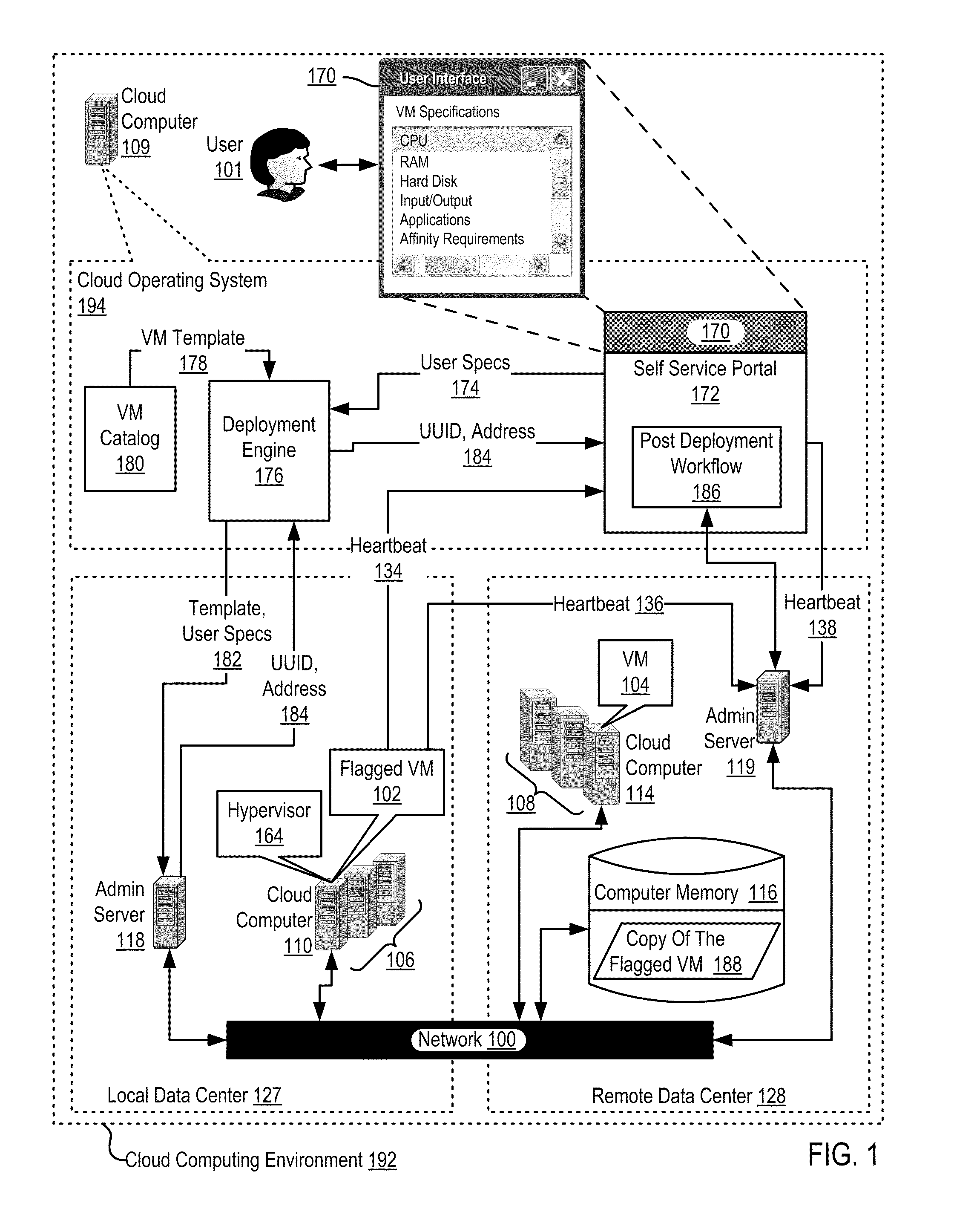
[0010]Example methods, apparatus, and products for deploying a virtual machine for disaster recovery in a cloud computing environment according to embodiments of the present invention are described with reference to the accompanying drawings, beginning with FIG. 1. FIG. 1 sets forth a functional block diagram of apparatus that deploys a virtual machine for disaster recovery in a cloud computing environment according to embodiments of the present invention. The apparatus in the example of FIG. 1 implements a cloud computing environment (192) that includes a virtual machine (‘VM’) (102) to be deployed for disaster recovery, where the VM is modules of automated computing machinery installed upon a cloud computer (110) disposed within a local data center (127). The local data center is said to be ‘local’ with respect to the subject VM. That is, the ‘local’ data center (127) is the data center in which the VM is deployed for disaster recovery. The apparatus in the example of FIG. 1 also ...


PUM


Abstract

Deploying a virtual machine in a cloud computing environment, the cloud computing environment including one or more virtual machines (‘VMs’), the VMs being modules of automated computing machinery installed upon cloud computers disposed within data centers, the cloud computing environment also including a cloud operating system and data center administration servers operably coupled to the VMs, including deploying, by the cloud operating system in a local data center, a VM, including flagging the VM for disaster recovery; storing, by the cloud operating system in computer memory in a remote data center, a copy of the flagged VM; and configuring, by the cloud operating system, the remote data center to replace data processing operations of the flagged VM in the local data center with data processing operations of the copy in the remote data center when the flagged VM in the local data center is lost through disaster.

Description

BACKGROUND OF THE INVENTION[0001]1. Field of the Invention[0002]The field of the invention is data processing, or, more specifically, methods, apparatus, and products for deploying a virtual machine for disaster recovery in a cloud computing environment.[0003]2. Description Of Related Art[0004]The development of the EDVAC computer system of 1948 is often cited as the beginning of the computer era. Since that time, computer systems have evolved into extremely complicated devices. Today's computers are much more sophisticated than early systems such as the EDVAC. Computer systems typically include a combination of hardware and software components, application programs, operating systems, processors, buses, memory, input / output devices, and so on. As advances in semiconductor processing and computer architecture push the performance of the computer higher and higher, more sophisticated computer software has evolved to take advantage of the higher performance of the hardware, resulting ...

Claims


Application Information

Patent Timeline
20 Oct 2011
Publication
US20110258481A1
IPC
G06F11/20
CPC
G06F11/20; G06F11/1484
Inventors
KERN, ERIC R.