Method and apparatus for retaining an ornament

a technology for ornaments and frames, applied in the direction of support devices, large fixed members, lighting support devices, etc., can solve the problem of not disclosing the mounting of ornaments to frames or plates

Active Publication Date: 2011-10-27
W SCHONBEK LLC
View PDF4 Cites 8 Cited by
  • Summary
  • Abstract
  • Description
  • Claims
  • Application Information

AI Technical Summary

Benefits of technology

[0008]In one embodiment of the invention, a method of retaining an ornament on a frame is provided. The method may include providing a pin having a first end and a second end, opposite the first end, the second end comprising a projection; inserting the first end of the pin through an aperture in the ornament and through a hole in the frame wherein the projection obstructs the aperture in the ornament; deforming the second end of the pin to provide a deformation of the second end that obstructs passage of the second end through the hole in the frame; and retaining the ornament on the frame by the projection of the first end of the pin and the deformation of the second end of the pin. In one aspect, the practice of deforming may comprise twisting the second end of the pin about an axis of the pin. In another aspect, wherein when the pin comprises a non-circular cross section, the method may further comprise, while twisting the second end of the pin, preventing rotation of the pin in the hole of the frame. This prevention of rotation may be effected by interference between the non-circular cross section of the pin and the hole in the frame.

Problems solved by technology

However, due to the fragility of these ornaments, care must be taken in mounting or retaining the ornament on the fixture, that is, to the structure or frame that provides the structural base of the fixture, without damaging the ornament or the frame.
Other means of engaging frames or plates are disclosed in U.S. Pat. Nos. 5,258,900 [Attorney ref 2350.412] and 5,577,838 [Attorney ref 2350.405]; however, these patents do not disclose the mounting of ornaments to frames or plates, but the engagement of plates with plates.

Method used


Image

  • Method and apparatus for retaining an ornament
  • Method and apparatus for retaining an ornament
  • Method and apparatus for retaining an ornament

Examples


Embodiment Construction

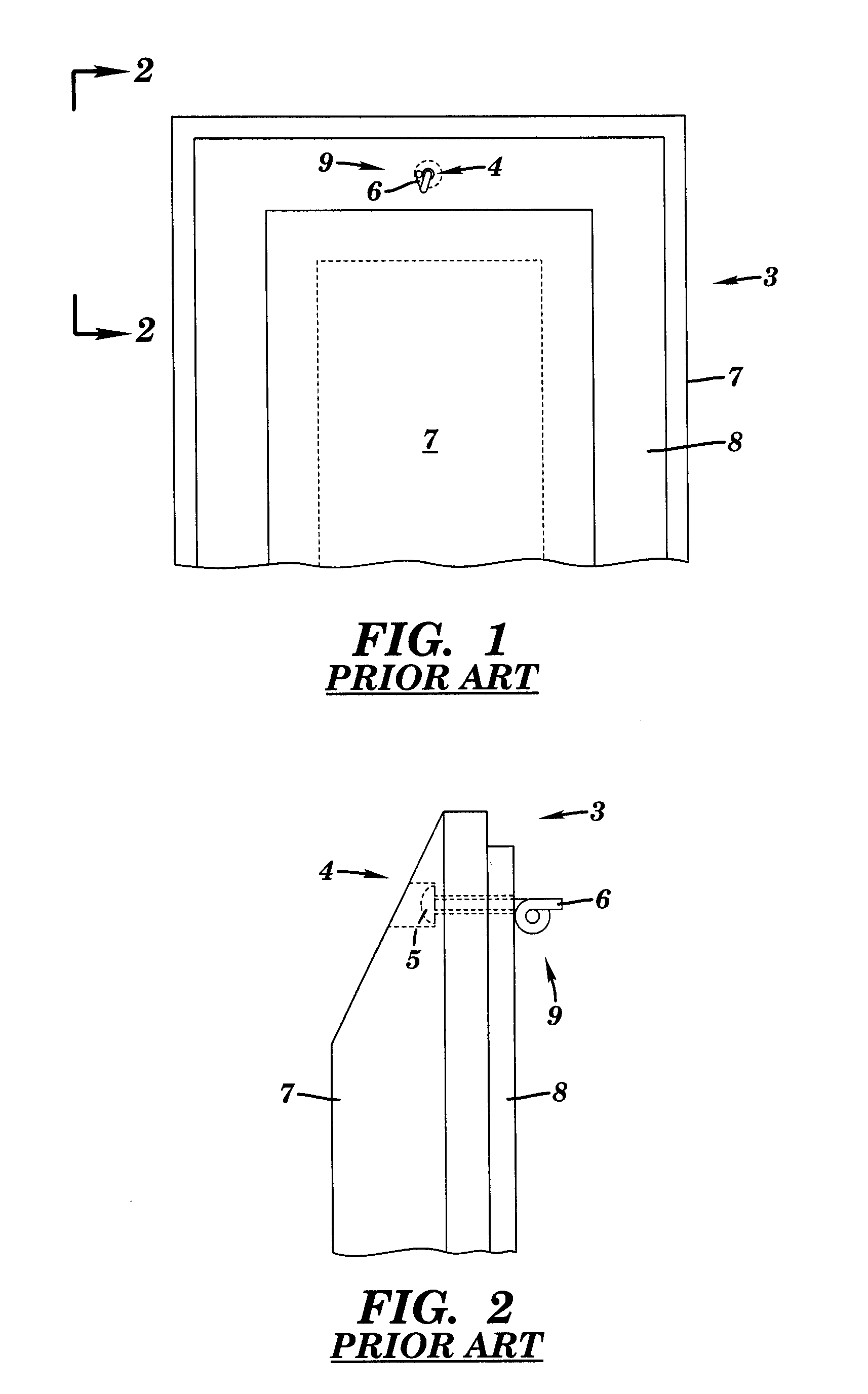
[0036]FIG. 1 is a rear view of a “pigtail” ornament mounting 3 according to the prior art. FIG. 2 is side elevation view of the “pigtail” ornament mounting 3 shown in FIG. 1 as viewed along lines 2-2 in FIG. 1. As shown, mounting 3 comprises a pin 4 having a head 5 and a distal end 6 opposite the head 5. The distal end 6 is inserted through a hole in an ornament 7 and a frame or plate 8. After insertion, the distal end 6 of pin 4 is twisted, for example, manually with an appropriate tool, such as, a needle-nose pliers, in a circular fashion to provide the so-called “pigtail”9. According to the prior art, the ornament 7 is retained on plate 8 between head 5 and pigtail 9.

[0037]However, it will be apparent to those of skill in the art that the manipulation of pin 4, especially, the twisting of distal end 6 to create pigtail 9 can be a cumbersome manual process. When constructing an ornamental fixture having numerous ornament mountings, such as, as chandeliers, wall sconces, lamps, and...


PUM

PropertyMeasurementUnit
thicknessesaaaaaaaaaa
lengthaaaaaaaaaa

Abstract

A method and apparatus for retaining an ornament, for example, an ornamental crystal, on a frame or plate is provided. The method includes providing a pin having a first end and a second end, opposite the first end, the second end comprising a projection, for example, a head; inserting the first end of the pin through an aperture in the ornament and through a hole in the frame wherein the projection obstructs the aperture in the ornament; deforming, for example, twisting, the second end of the pin to provide a deformation of the second end that obstructs passage of the second end through the hole in the frame; and retaining the ornament on the frame by the projection of the first end of the pin and the deformation of the second end of the pin. Aspects of the invention facilitate the mounting of ornaments to ornamental fixtures, for example, chandeliers.

Description

BACKGROUND OF THE INVENTION[0001]1. Technical Field[0002]The present invention generally relates to methods and apparatus for retaining ornaments on an ornamental frame. More particularly, the present invention relates to methods and apparatus for retaining ornaments on a frame by means of a pin that is passed through the ornament and the frame and then deformed to retain the ornament.[0003]2. Description of Related Art[0004]Designers of ornamental fixtures, for example, lighting fixtures, such as, chandeliers and wall sconces, often use ornaments to enhance the appearance of their fixtures. These ornaments may consist of any conventional ornaments, such as, ceramic beads or glass crystals, and typically include an aperture or hole that provides a point of attachment to the fixture. However, due to the fragility of these ornaments, care must be taken in mounting or retaining the ornament on the fixture, that is, to the structure or frame that provides the structural base of the fixt...

Claims


Application Information

Patent Timeline
Patent Type & Authority Applications(United States)
IPC IPC(8): B23P11/00B23K31/02B23K1/20B23K37/00F16M13/02B23K11/34
CPCF21V5/06F21V17/16Y10T29/53996Y10T29/49908Y10T29/53909Y10T29/49915Y10T29/53791Y10T29/53513Y10T29/53709Y10T29/53522
Inventor LY, THOSCHUYLER, ANDREW
Owner W SCHONBEK LLC
Why Eureka
Try Eureka