
Vertical planter

a planter and vertical technology, applied in the field of vertical planters, can solve the problems of affecting the appearance of the planter, the method does not fare well over time, and the fabric is covered with moss and sediment, and on close inspection is unsightly,

Inactive Publication Date: 2011-10-27
BAKER RICHARD L
View PDF10 Cites 122 Cited by
  • Summary
  • Abstract
  • Description
  • Claims
  • Application Information

AI Technical Summary

Benefits of technology

[0019]According to yet another feature of the invention, the individual planter units can be removably supported to a wall so that the lower planter units do not have to support the weight of the overlying planter units. An array of planter units can be fastened to the wall and when populated with mature plants, the entire wall appears covered with vegetation.

Problems solved by technology

This method does not fare well over time.
The fabric becomes coated with moss and sediment and upon close inspection is unsightly.
The felt material often tears and shows extreme wear over only a few years in the environment.
Repairs are only achieved by re-stuffing soil into the holes on the wall, which is both difficult and messy.
Loose-soil systems should not be used in areas where there will be a lot of public interaction as they are quite messy and lose their soil little by little over time as their medium wets and dries, falling out onto the floor in front, if not properly designed.
Most importantly, because these systems can easily have their medium blown away by wind-driven rain or heavy winds, they should not be used in applications over eight feet high.
Mat media are quite thin, even in multiple layers, and as such cannot support vibrant root systems of mature plants for more than three to five years before the roots overtake the mat and water is not able to adequately wick through the mats.
It is important to note that mat systems are particularly water inefficient and often require constant irrigation due to the thin nature of the medium and its inability to hold water and provide a buffer for the plant roots.
This inefficiency requires that these systems have a water re-circulation system put into place at an additional cost.
The downside is that these systems are often very expensive to install.

Method used


Image

  • Vertical planter
  • Vertical planter
  • Vertical planter

Examples


Embodiment Construction

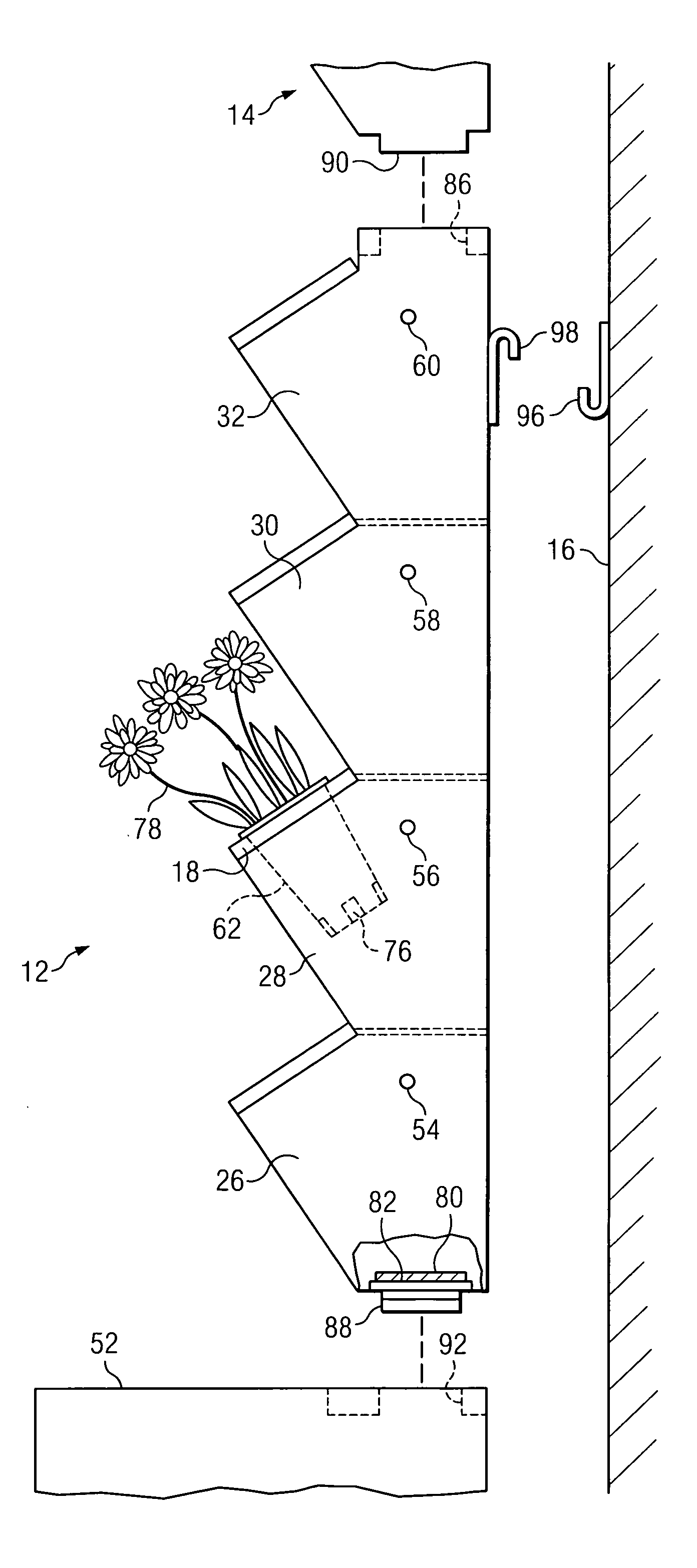
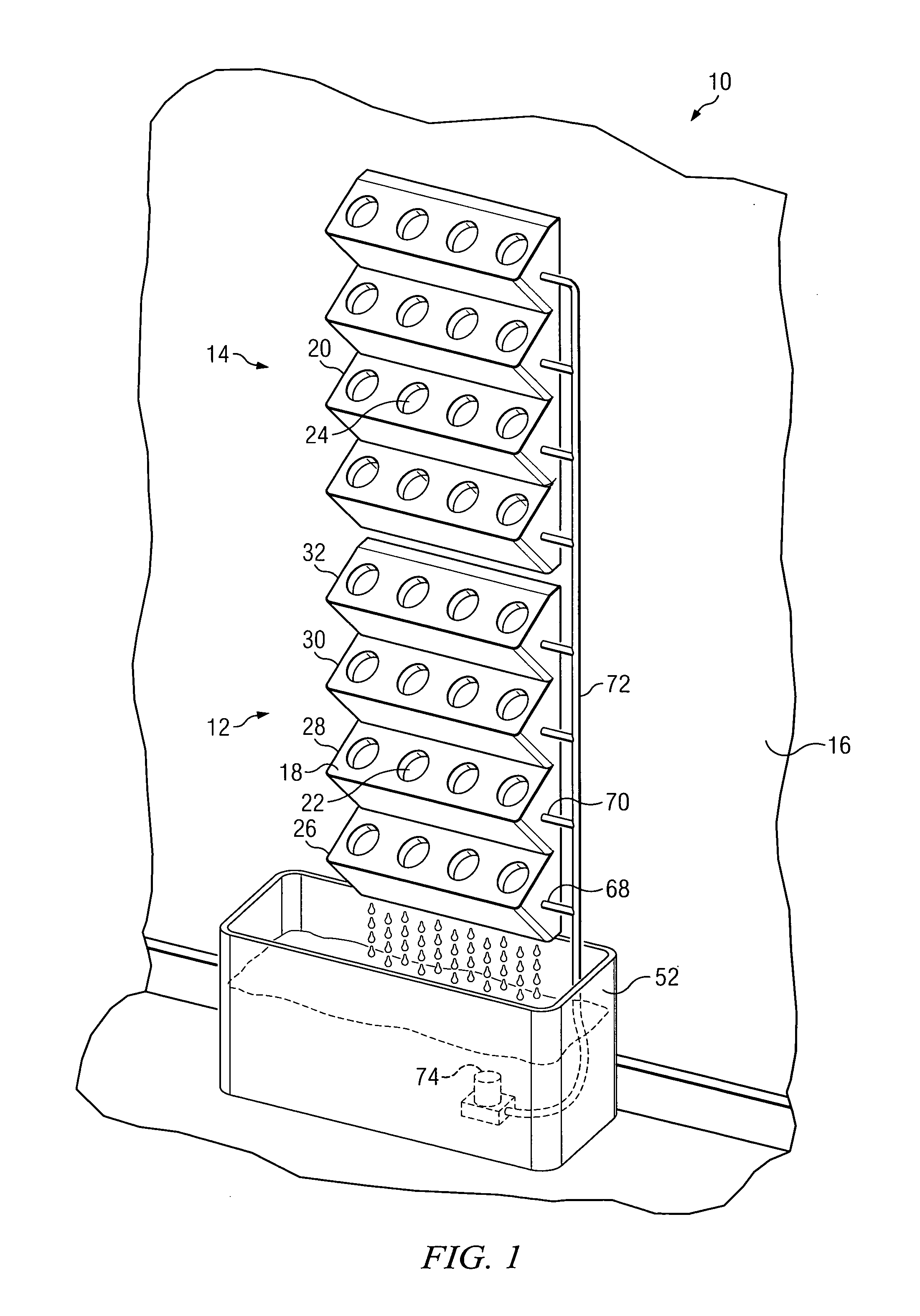
[0040]According to one embodiment of the invention, FIG. 1 illustrates a vertical planter 10 that is modular in construction so that different units can be arranged together to form a single vertical planter to accommodate a desired number of plants. The vertical planter 10 includes a first planter unit 12 and a second planter unit 14 that is mounted on top of the first planter unit 12. The vertical planter 10 is fastened to a wall 16 which can be of any type of structure, including the studs to which sheet rock is nailed, a mason or brick wall, or any other type of interior or outside vertical wall. Moreover, the vertical planter can be mounted to a wall of a building, or a free standing wall, fence or any other type of vertical support.

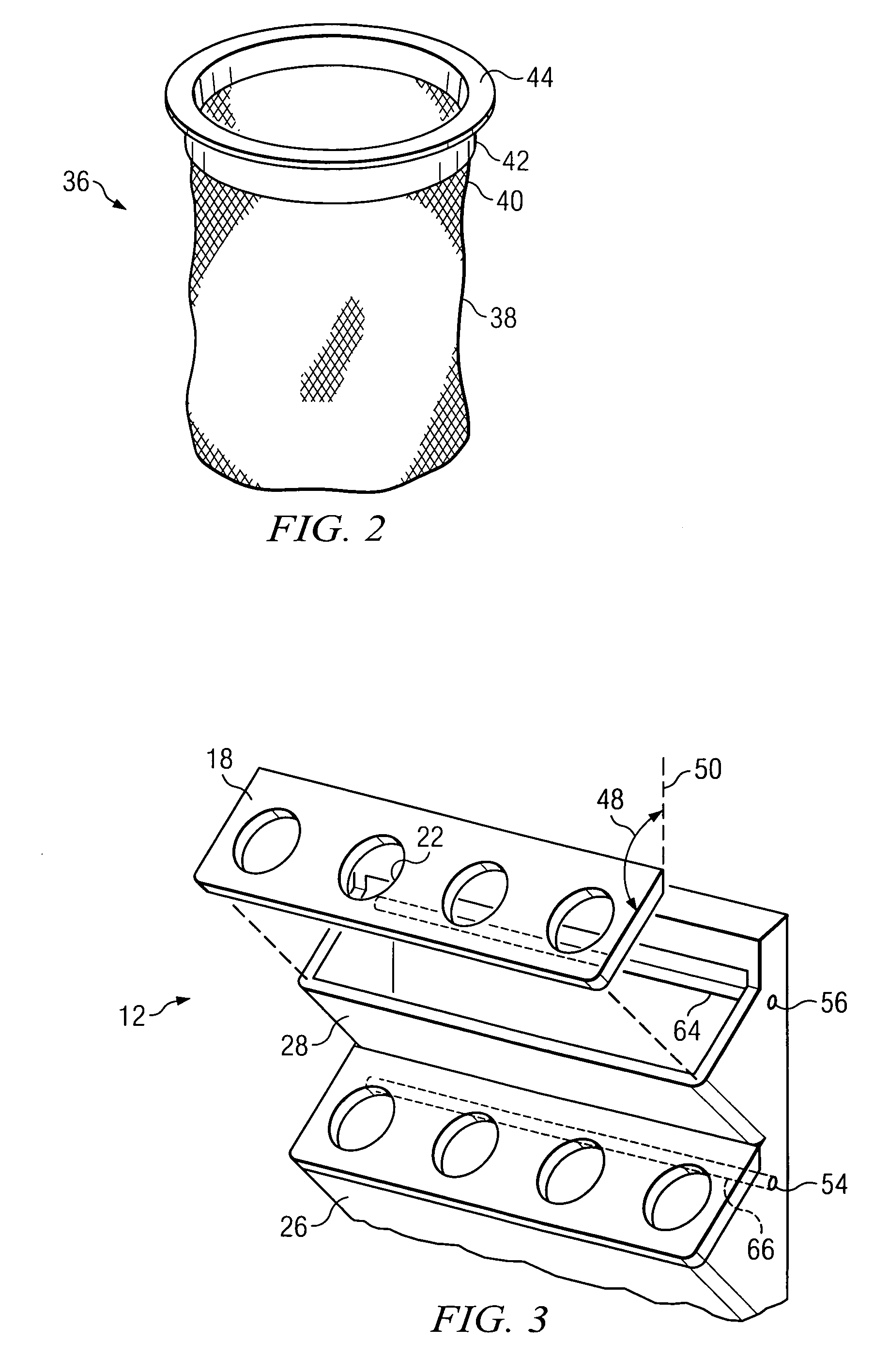
[0041]The planter units, such as unit 12, can be constructed from a variety of structurally strong, water tight materials, such as plastic. Since each unit of the vertical planter 10 is constructed in an identical or similar manner, only the bottom ...


PUM


Abstract

A vertical planter includes stackable planter units each with plural sections in which plural plants can be planted. Each section of a planter unit can have a removable faceplate for placing soil in the planter section and planting plants in the soil, or potted plants can be placed in the faceplate openings. Water is provided to each planter section via a drip irrigation tube fed from a main water supply tube that extends to each planter unit. The drain water from each planter unit drains down through an underlying planter unit and into an underlying water reservoir.

Description

CROSS REFERENCE TO RELATED APPLICATIONS[0001]This non-provisional patent application claims the benefit of pending U.S. provisional patent applications a) Ser. No. 61 / 343,201 filed Apr. 19, 2010, entitled “Vertical Garden Modular Plant Core,” and b) Ser. No. 61 / (not yet received) , filed Mar. 11, 2011, named inventor—Richard L. Baker, and entitled “Self-Contained Vertical Garden.”TECHNICAL FIELD OF THE INVENTION[0002]The present invention generally relates to planters for greenery, and in particular to vertical planters where one set of plants is oriented generally above another set of plants.BACKGROUND OF THE INVENTION[0003]Green walls are becoming popular because of the pleasant appearance and the feeling of purity of the environment. A green wall is a wall, either free-standing or part of a building, that is partially or completely covered with vegetation and, in some cases, soil or an inorganic growing medium. The vegetation for a green facade is generally attached on outside wa...

Claims


Application Information

Patent Timeline
Patent Type & Authority Applications(United States)
IPC IPC(8): A01G9/02
CPCA01G9/023A01G9/025
Inventor BAKER, RICHARD L.
Owner BAKER RICHARD L
Learn More