Tubular handling device

Inactive Publication Date: 2011-10-27
FIRST SUS +1
View PDF1 Cites 5 Cited by
  • Summary
  • Abstract
  • Description
  • Claims
  • Application Information

AI Technical Summary

Benefits of technology

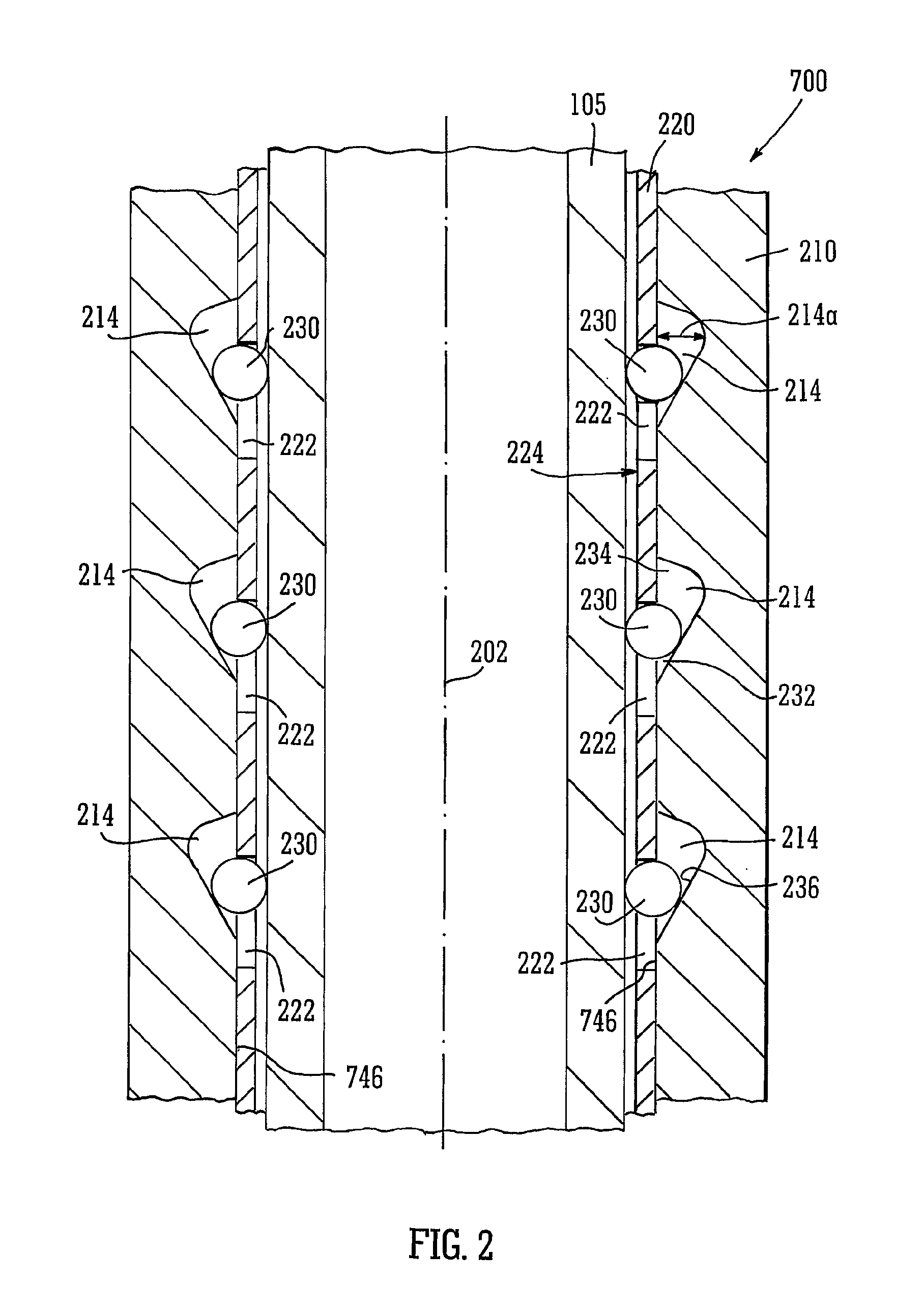
[0030]Thus, when said lifting eyes are each attached to a lifting cable that lifts the clamp segments, the segments separate sufficiently to release any tubular clamped between the clamp-segments. That is to say, preferably the angle of inclination with respect to the longitudinal axis of the frusto-conical surfaces is greater than the angle of inclination of the recess bases. The latter is preferably between 3 and 10 degrees, preferably between 5 and 8 degrees. The former is preferably between 10 and 20 degrees, and more preferably between 13 and 16 degrees.
[0031]Preferably, the tool is designed to clamp on tubular members whose diameter is such that, when the clamp-segments abut one another with mating side faces and the frustoconical surfaces a

Problems solved by technology

However, if the tubular has peripheral extensions then the slotted member cannot necessarily move over such extensions during positioning of

Method used


Image

  • Tubular handling device
  • Tubular handling device
  • Tubular handling device

Examples


Embodiment Construction

[0039]It is to be understood that the following disclosure provides many different embodiments, or examples, for implementing different features of various embodiments. Specific examples of components and arrangements are described below to simplify the present disclosure. These are, of course, merely examples and are not intended to be limiting. In addition, the present disclosure may repeat reference numerals and / or letters in the various examples. This repetition is for the purpose of simplicity and clarity and does not in itself dictate a relationship between the various embodiments and / or configurations discussed. Moreover, the formation of a first feature over or on a second feature in the description that follows may include embodiments in which the first and second features are formed in direct contact, and may also include embodiments in which additional features may be formed interposing the first and second features, such that the first and second features may not be in d...


PUM


Abstract

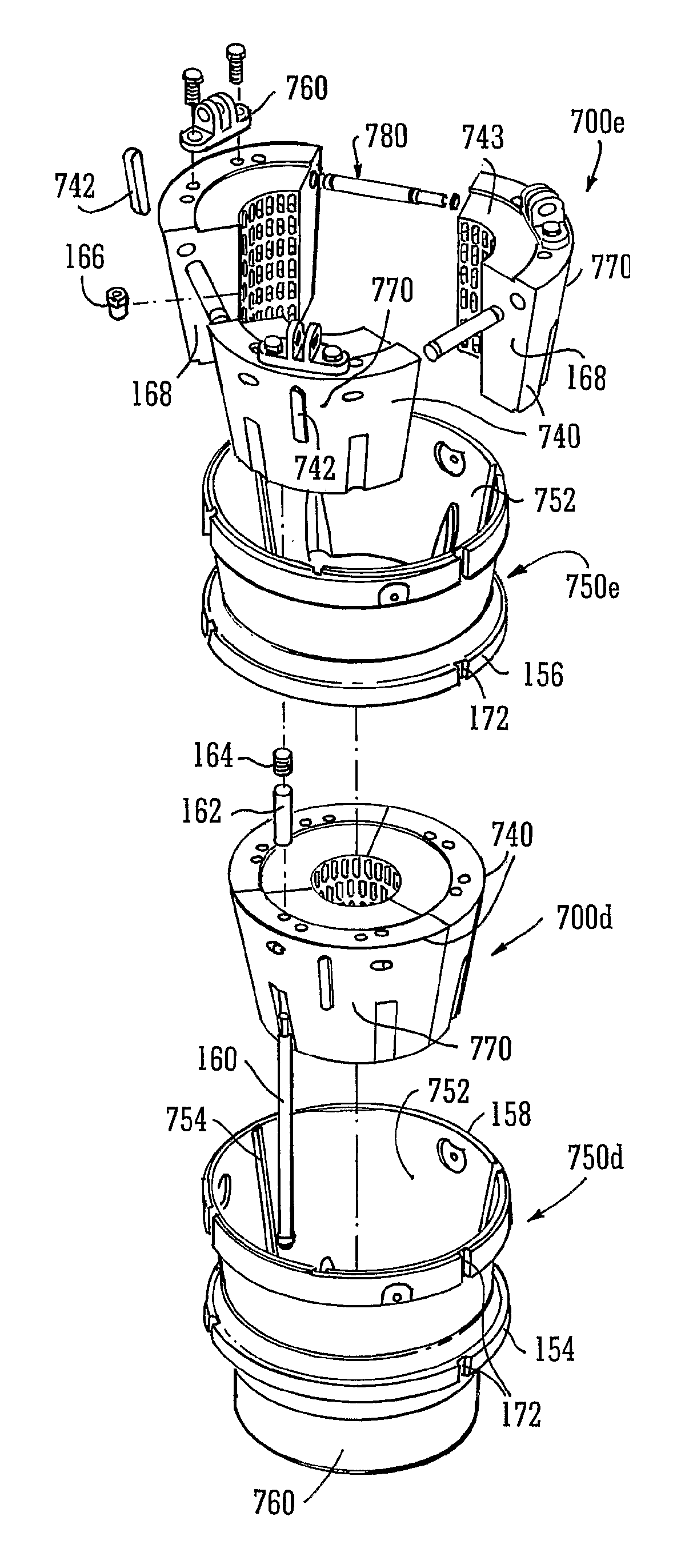
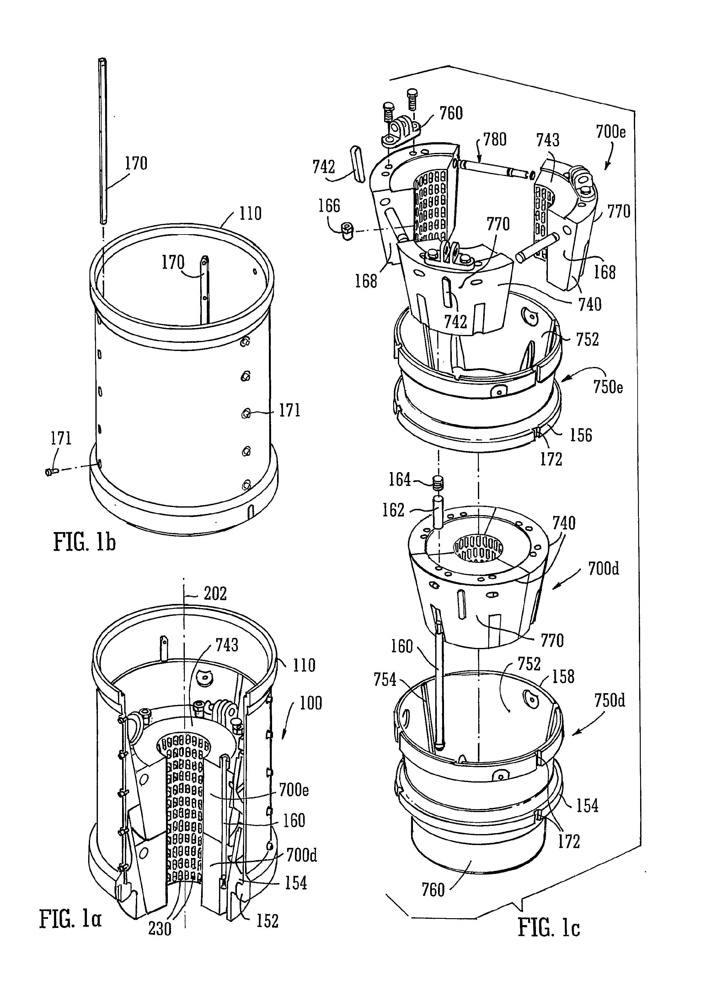
A tubular member handling apparatus is a gripping tool (100) in the form of a body (110) having a longitudinal axis (202) and formed by a plurality of sleeves (750) connected end to end, each sleeve including a frusto-conical bore 752 centered on said longitudinal axis; a clamp member (700) in each sleeve formed by clamp-segments (740), each having side faces (168), end faces (743), a frusto-conical exterior surface (741) adapted to match said frusto-conical bore, and a cylindrical interior surface (745); cage-segments (220) connected to said interior surface and having a plurality of windows (222) partially closing recesses (214) in said interior surface, which recesses are elongate in said longitudinal direction, house a roller (230) and have a base (236) inclined in said longitudinal direction so that, at a lower end (232) of each recess the roller protrudes through said window and at an upper end (234) thereof the roller protrudes less or not at all; a bias mechanism 780, urging said clamp-segments apart from each other in a peripheral direction; connection means (160) between adjacent clamp segments so that they move together when one is moved axially.

Description

[0001]This invention relates to a device for handling circular cylindrical tubular objects, with or without intervening bulges or flanges at their ends or intermediate their length. Furthermore it relates to a device that can grip such a tubular object not just for the purpose of lifting the object (in a direction including vertically upwardly in a direction parallel a longitudinal axis of the object), but also for the purpose of applying torque to the object about said longitudinal axis.BACKGROUND[0002]The drilling of subterranean wells involves assembling tubular strings, such as casing strings and drill strings, each of which comprises a plurality of heavy, elongated tubular segments extending downwardly from a drilling rig into a wellbore. The tubular string consists of a number of threadedly engaged tubular segments.[0003]Conventionally, workers use a labor-intensive method to couple tubular segments to form a tubular string. This method involves the use of workers, typically a...

Claims


Application Information

Patent Timeline
IPC IPC(8): E21B19/10
CPCE21B19/07E21B19/18
Inventor HUGHES, PAUL ANTHONYYOUSEF, FAISAL J.
Owner FIRST SUS
Why Eureka
Try Eureka