Structure for a terminal in an electric connector

Inactive Publication Date: 2011-06-02
TYCO ELECTRONICS (SHANGHAI) CO LTD
View PDF3 Cites 0 Cited by
  • Summary
  • Abstract
  • Description
  • Claims
  • Application Information

AI Technical Summary

Benefits of technology

[0019]Refer to FIG. 3a, in the structure of a cantilevered beam, according to the structure of the bended beam (for example, the bended beam has a curved surface of certain curvature when under an external force), an assistant supporting feature is provided under the bended beam. The assistant supporting feature has a curved surface which mates with the curved surface of the bended beam. When being exerted an external force, the bended beam is completely supported on the mating curved surface of the supporting feature. Based on the mechanical principle of the beam structure, when the bended beam is fully supported by the curved surface of the supporting feature, so as to form an even stress distribution on the whole beam (including the fixed end and the free end thereof) as show in FIG. 3b. Thus, for the cantilevered beam, a maximum deformation tolerance and an increased endurance stress limit are achieved.
[0020]As apparent from the above, the structure for a terminal in an electric connector of the present invent

Problems solved by technology

That is to say, it is unfeasible to change the stress distribution on the beam-type terminal sheet by varying the thickness of such terminal sheet.
This, however, improves merely the tolerance, of deformation of the beam, without h

Method used


Image

  • Structure for a terminal in an electric connector
  • Structure for a terminal in an electric connector
  • Structure for a terminal in an electric connector

Examples


Example

[0028]Exemplary embodiments of the present disclosure will be described hereinafter in detail with reference to the attached drawings, wherein the like reference numerals refer to the like elements. The present disclosure may, however, be embodied in many different forms and should not be construed as being limited to the embodiment set forth herein; rather, these embodiments are provided so that the present disclosure will be thorough and complete, and will fully convey the concept of the disclosure to those skilled in the art.

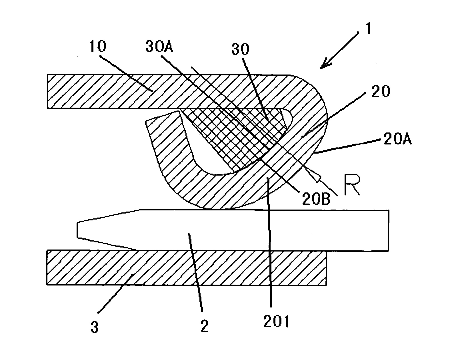
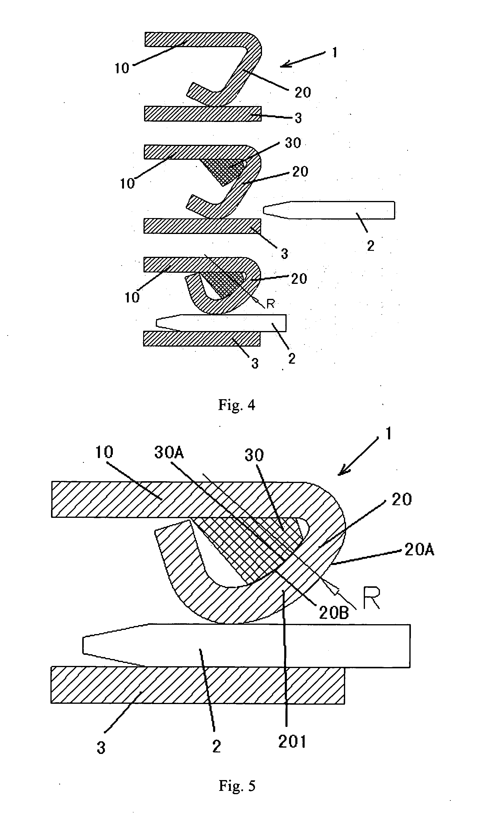
[0029]For easier understanding, hereafter are the detailed descriptions and illustrations about the present invention by taking the structure for a terminal in an electric connector as an example. Particularly, the electric connector mainly comprises an insulating housing and a terminal provided in the insulating housing and adapted for electrical connection. The terminal has a splicing portion to be mated with a mating terminal of the mating electric connect...


PUM


Abstract

The present invention relates to a field of electric connector, and in particular, to a structure for a terminal in an electric connector. In one preferred embodiment, a structure for a terminal in an electric connector is provided. The structure comprises: a terminal fixation part; a terminal elastic part; and an overstress prevention element. The terminal elastic part is extended from the terminal fixation part, wherein the terminal elastic part enables elastic deformation relative to the terminal fixation part and is configured to bend toward the terminal fixation part upon application of an external force. The overstress prevention element is provided between the terminal fixation part and the terminal elastic part, and is adapted for restricting overbending of the terminal elastic part. Furthermore, the present invention provides an electric connector incorporating the structure for the terminal therein. According to the present invention, the structure for a terminal in an electric connector realizes an overstress preventing performance. Furthermore, the structure for the terminal in the electric connector is compact in structure, has high efficiency in material utilization and low cost, and enables precise control of the stress on the structure for the terminal.

Description

CROSS-REFERENCE TO RELATED APPLICATION[0001]This application claims the benefit of Chinese Patent Application No. 200910258032.0 filed on Dec. 1, 2009 in the State Intellectual Property Office of China, the disclosure of which is incorporated herein by reference.BACKGROUND OF THE INVENTION[0002]1. Field of the Invention[0003]The present invention relates to a field of electric connector, and in particular, to a structure for a terminal of an electric connector.[0004]2. Description of the Related Art[0005]It has been known that in an electric connector in the prior art, the terminal sheet generally provides a locking force or a retention force for the connection or the contact between the terminals sheet. In general, the terminal sheet usually adopts a cantilevered beam structure, such as a beam.[0006]With the reference of FIG. 1a and FIG. 1b, they schematically illustrate the characteristics of the beam structure. FIG. 1a shows a basic mechanical schematic view of a cantilever beam ...

Claims


Application Information

Patent Timeline
IPC IPC(8): H01R4/48
CPCH01R43/16H01R13/113
Inventor YANG, YUCHENGUANCO, ANDRE E.
Owner TYCO ELECTRONICS (SHANGHAI) CO LTD
Why Eureka
Try Eureka