
Twist-axle with longitudinally-varying wall thickness

a twistaxle and longitudinal technology, applied in the direction of resilient suspensions, interconnection systems, vehicle springs, etc., can solve the problems of cross-beam member twisting, increased manufacturing and material costs, and durability concerns

Active Publication Date: 2011-10-27
ARCELORMITTAL TUBULAR PRODS CANADA
View PDF7 Cites 18 Cited by
  • Summary
  • Abstract
  • Description
  • Claims
  • Application Information

AI Technical Summary

Benefits of technology

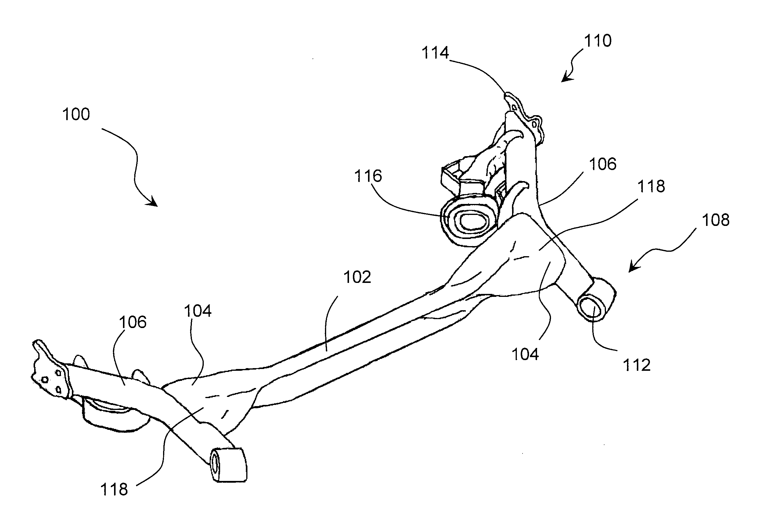
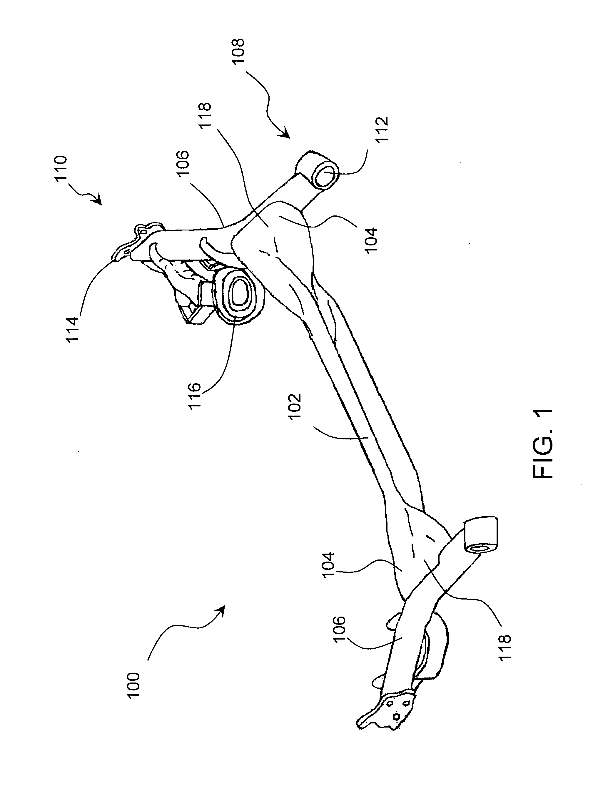
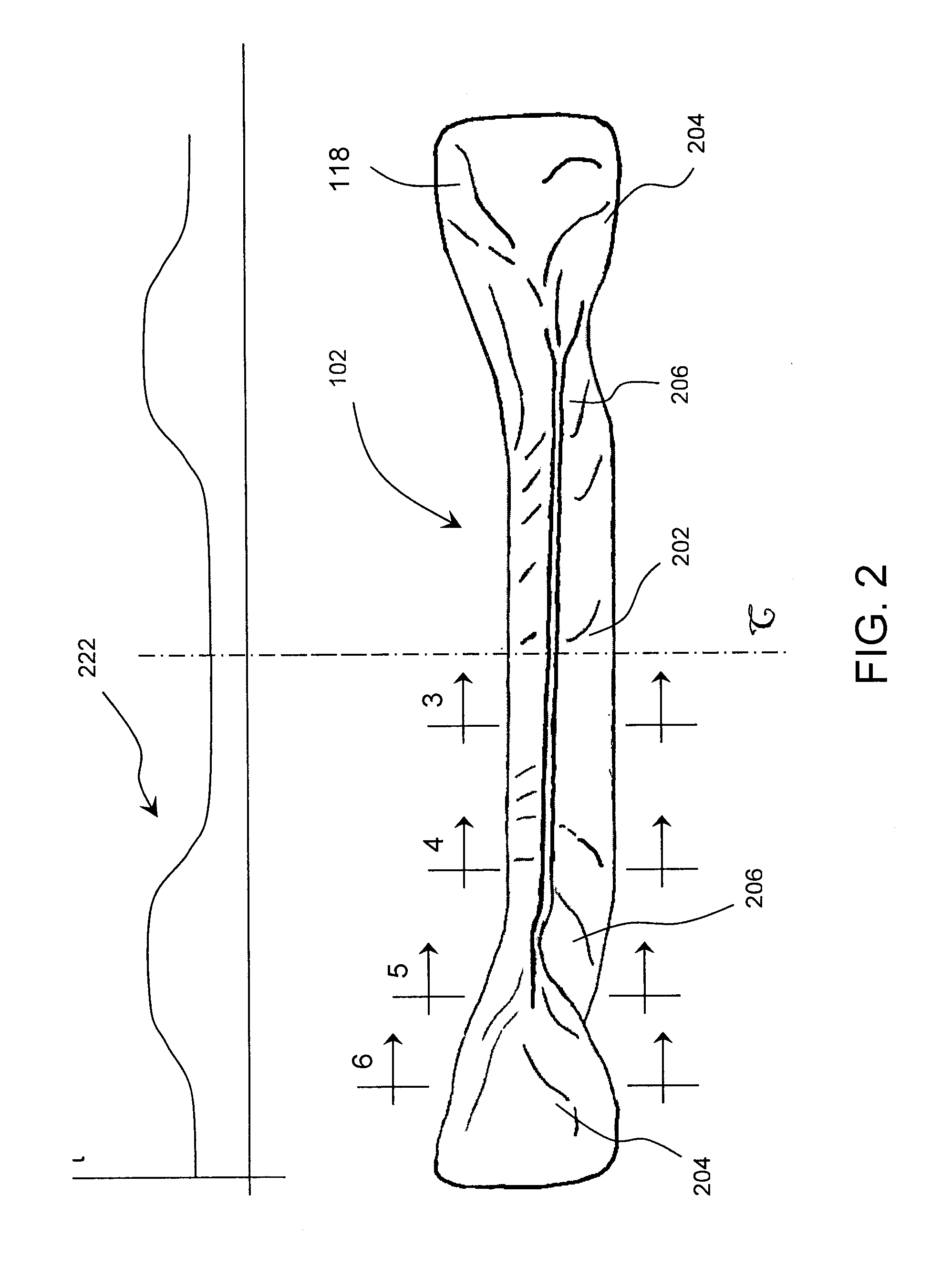
[0007]In one embodiment, the cross-beam member has two connection regions and a central mid-section between the two connection regions. The central portion is torsionally elastic and the connection regions are torsionally stiff. The connection regions are where the trailing arms are rigidly secured or linked to the cross-beam member. The tubular cross-beam member has a wall thickness varying longitudinally from the torsionally elastic central portion to each of the torsionally stiff connection regions. In one feature of the invention, the wall thickness is larger in at least a portion of the connection regions than in the central section. In another feature of the invention, the wall thickness varies smoothly along the cross-beam member from the torsionally elastic central portion to each of the torsionally stiff connection regions.

Problems solved by technology

When the road wheels are unequally displaced relative to the vehicle's frame, such as when the wheels encounter an uneven surface or when the vehicle is turning, the unequal displacement causes the trailing arms to pivot by different amounts, thereby resulting in twisting of the cross-beam member.
These proposals, however, require additional manufacturing and material costs.
However, as a twisting force is applied to such a cross-beam member, stresses tend to concentrate in the transition zones located between the mid-section and the end sections, which may cause durability concerns.
This approach, however, introduces additional manufacturing steps and also requires additional heat treatment equipment.

Method used


Image

  • Twist-axle with longitudinally-varying wall thickness
  • Twist-axle with longitudinally-varying wall thickness
  • Twist-axle with longitudinally-varying wall thickness

Examples


Embodiment Construction

[0027]The description which follows and the embodiments described therein are provided by way of illustration of an example, or examples, of particular embodiments of the principles of the present invention. These examples are provided for the purposes of explanation, and not limitation, of those principles and of the invention. In the description which follows, like parts are marked throughout the specification and the drawings with the same respective reference numerals.

[0028]FIG. 1 illustrates a twist-axle 100 in a suspension structure, in particular, a rear suspension structure. The twist-axle 100 includes a cross-beam member 102. The cross-beam member is generally elongated, having two opposite ends 104. The twist-axle 100 is typically provided with two side trailing arms 106.

[0029]Each trailing arm 106 has a first end 108 and a second end 110 as illustrated in FIG. 1. The first end 108 is adapted to be pivotally connected to a vehicle's frame (not shown) through, for example, ...


PUM

PropertyMeasurementUnit
thicknessaaaaaaaaaa
thicknessaaaaaaaaaa
thicknessaaaaaaaaaa

Abstract

The invention relates to a twist-axle that includes a cross-beam member and two trailing arms, each trailing arm rigidly secured to the cross-beam member in one of two connection regions of the cross-beam member or formed integrally with and extending from one of the two connection regions. The cross-beam member is formed from a tubular blank and has a torsionally elastic central portion and two torsionally stiff connection regions. The cross-beam member has a wall thickness that varies longitudinally along the length of the cross-beam member from the torsionally elastic central portion to each of the torsionally stiff connection regions.

Description

FIELD OF INVENTION[0001]The invention relates generally to the field of tubular components for suspension and chassis structures, and has particular application to tubular twist-axle of a vehicle.BACKGROUND OF INVENTION[0002]In a vehicle, a twist-beam or twist-axle is often used as a rear suspension structure. A twist-axle has two trailing arms for connecting road wheels to a vehicle's frame and a cross-beam member linking the trailing arms to form an integral body. Each trailing arm is pivotally connected to a vehicle's frame. When the road wheels are unequally displaced relative to the vehicle's frame, such as when the wheels encounter an uneven surface or when the vehicle is turning, the unequal displacement causes the trailing arms to pivot by different amounts, thereby resulting in twisting of the cross-beam member. The inherent torsional stiffness or resistance of the cross-beam member provides a restoring force to the unevenly displaced wheels.[0003]For ride comfort and contr...

Claims


Application Information

Patent Timeline
Patent Type & Authority Applications(United States)
IPC IPC(8): B60G21/05B21D53/88
CPCB21C1/24B21D53/88B21K1/12B60G21/051Y10T29/49622B60G2202/136B60G2206/20B60G2206/81B60G9/00B60G2200/21B60G2204/1434B60G2206/012B60G2206/202B60G2206/30B60G2206/81035B60G2206/8402B60G2206/8403B21C37/16B60G21/05
Inventor LEPRE, STEFANO
Owner ARCELORMITTAL TUBULAR PRODS CANADA
Learn More