Motor-pump unit

a technology of motor housing and motor housing, which is applied in the direction of piston pumps, positive displacement liquid engines, liquid cleaning, etc., can solve the problems of wasting heat, affecting the efficiency of the motor housing, and requiring considerable production expenditure. , to achieve the effect of wasting heat and producing cost-effectively

Active Publication Date: 2014-06-05
ALFRED KARCHER GMBH & CO KG
View PDF4 Cites 3 Cited by
  • Summary
  • Abstract
  • Description
  • Claims
  • Application Information

AI Technical Summary

Benefits of technology

[0010]The motor-pump unit in accordance with the invention is characterized by cost-effective production and simple assembly as provision of the cooling channel merely requires the two housing parts of the motor housing to be joined together.
[0015]In an advantageous embodiment of the motor-pump unit in accordance with the invention, particularly simple assembly is achieved by the first housing part and the second housing part being adapted to be joined together in the axial direction in relation to the longitudinal axis of the electric motor, thereby forming the cooling channel.
[0024]It is expedient for the first housing part and / or the second housing part to comprise a side wall surrounding the electric motor in the circumferential direction and a bottom wall covering the electric motor at an end face, with an area of the side wall that is adjacent to the cooling channel having a larger wall thickness than the bottom wall. Such a configuration has the advantage that in the area adjacent to the cooling channel, the motor housing has a relatively large wall thickness which imparts a high heat conductivity to the motor housing so that waste heat from the electric motor can be conducted particularly effectively by way of the area of the side wall of larger wall thickness to the cooling channel, from which the waste heat can be dissipated by way of the liquid flowing through the cooling channel. In areas of the motor housing at a larger distance from the cooling channel, on the other hand, the wall thickness of the motor housing is kept lower. The weight of the motor housing can be thereby reduced, and the amount of material used for producing the motor housing can also be reduced. This lowers the production costs.
[0032]The first housing part and / or the second housing part is / are preferably made of metal. In particular, it may be provided that both housing parts are constructed as aluminum or zinc diecastings. This makes it possible for the motor housing to be produced cost-effectively and also has the advantage that waste heat from the electric motor can be dissipated particularly effectively to the liquid flowing through the cooling channel.

Problems solved by technology

However, this requires considerable heat exchanger surfaces and so air cooling is only possible with spatially extended motor-pump units.
However, the embedding of a steel pipe in the housing wall of the motor housing requires considerable production expenditure and involves substantial costs.
However, the provision of the cavity for the cooling liquid requires an additional plastic hood, which has to be placed on the motor housing in an additional assembly step.

Method used


Image

  • Motor-pump unit
  • Motor-pump unit
  • Motor-pump unit

Examples


Embodiment Construction

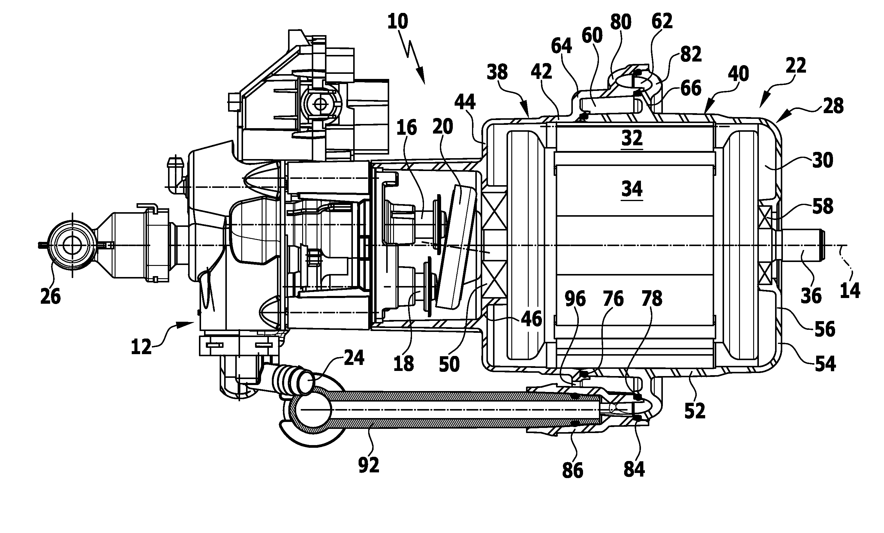
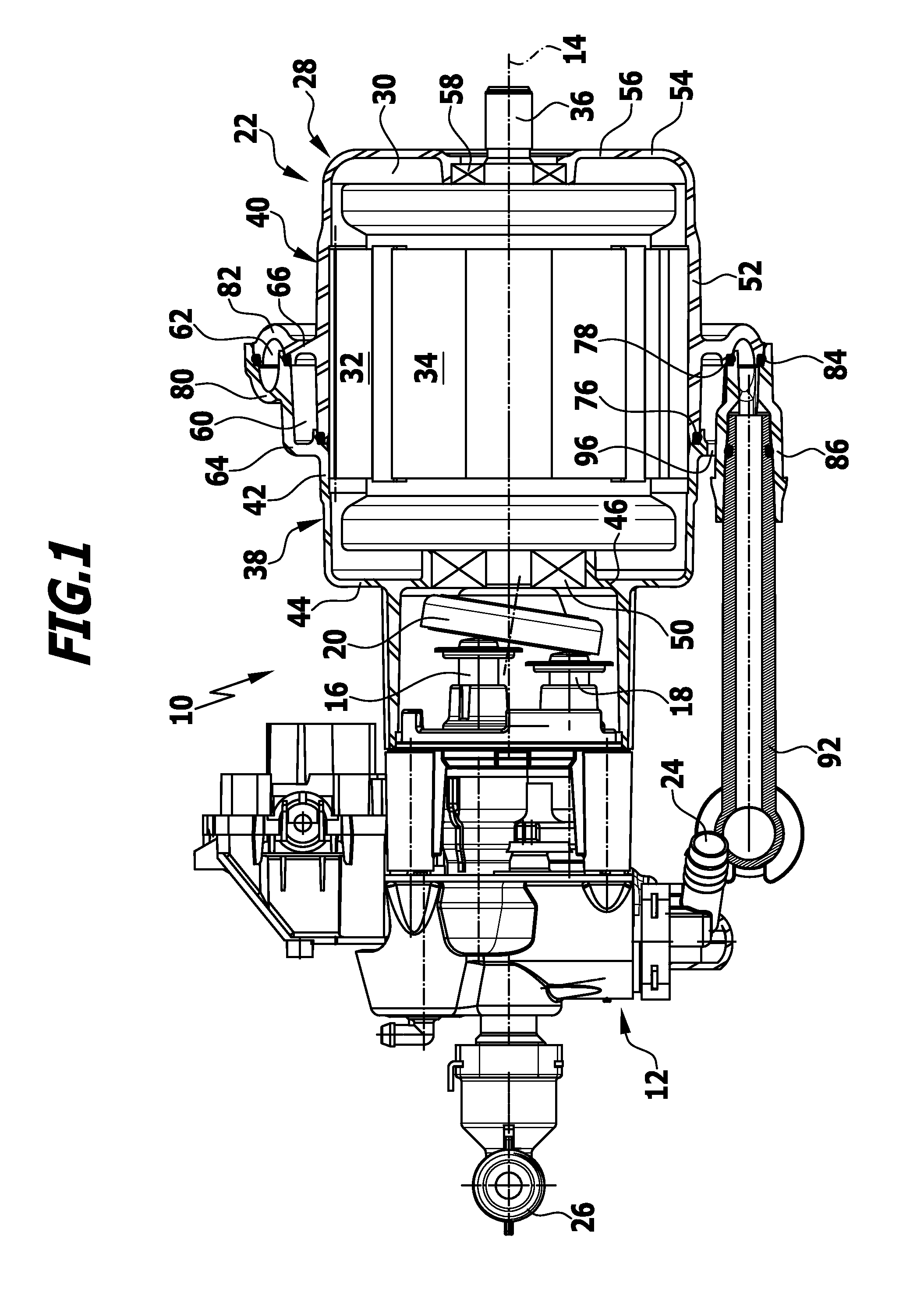
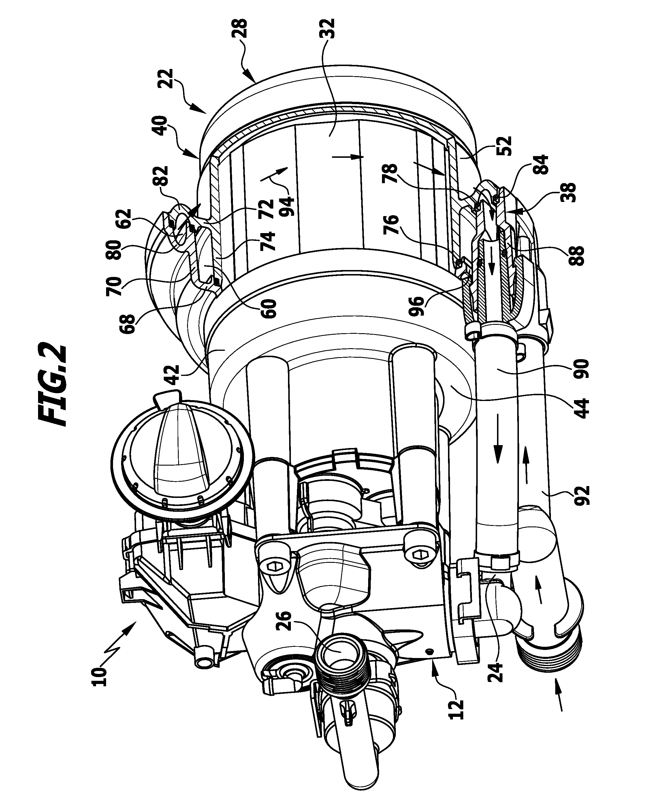
[0036]A motor-pump unit 10 in accordance with the invention, which is used in high-pressure cleaning appliances, is shown schematically in the drawings. It comprises a pump 12 which, in the illustrated embodiment, is constructed as a piston pump and comprises several pistons movable back and forth parallel to the longitudinal axis 14 of the motor pump unit 10. A first piston 16 and a second piston 18 are shown in FIG. 1. The pistons 16, 18 abut against a swash plate 20, which is made to rotate by an electric motor 22. The pistons 16, 18 each project in the usual manner into a pumping chamber, not shown in the drawings in order to provide a better overview, so that during the movement of the pistons 16, 18 back and forth, liquid which is to be pressurized by the pump 12 can be taken in by a suction inlet 24 of the pump 12 and discharged by way of a pressure outlet 26 of the pump. A pressure hose, not shown in the drawings, carrying at its free end a spray gun or a spray lance, for ex...


PUM


Abstract

A motor-pump unit includes an electric motor and a pump. The electric motor has a motor housing, on the outside of which a cooling channel is arranged. The pump has a suction inlet and a pressure outlet. Liquid to be pressurized can be fed by way of the cooling channel to the suction inlet. In order that the motor-pump unit can be produced and assembled more cost-effectively, the motor housing includes a first housing part and a second housing part, which are connectable to each other in a liquid-tight manner and between them form the cooling channel.

Description

CROSS-REFERENCE TO RELATED APPLICATIONS[0001]This application is a continuation of international application number PCT / EP2011 / 064026, filed on Aug. 15, 2011, which is incorporated herein by reference in its entirety and for all purposes.BACKGROUND OF THE INVENTION[0002]The invention relates to a motor-pump unit for a high-pressure cleaning appliance with an electric motor having a motor housing, on the outside of which a cooling channel is arranged, and with a pump driven by the electric motor and having a suction inlet for taking in liquid to be pressurized and a pressure outlet for discharging pressurized liquid, liquid to be pressurized being fed by way of the cooling channel to the suction inlet.[0003]By means of such motor-pump units, a cleaning liquid, preferably water, can be pressurized and subsequently directed at an article to be cleaned. For this purpose, in particular, a high-pressure hose carrying, for example, a spray gun or a spray lance at its free end can be connec...

Claims


Application Information

Patent Timeline
Patent Type & Authority Applications(United States)
IPC IPC(8): F04D29/58
CPCF04B1/122F04B17/03F04B17/06F04B39/064F04B53/08H02K7/14B08B2203/0223H02K5/203H02K5/20F04D29/588
Inventor NATHAN, ROBERTGRUBER, BERNHARD
Owner ALFRED KARCHER GMBH & CO KG
Why Eureka
Try Eureka