System and method for successive matrix transposes

a matrix and transposal technology, applied in the field of successive matrix transposal, can solve the problems of high area requirement and high software overhead associated with writing and reading the nn matrix

Inactive Publication Date: 2011-10-27
SAMSUNG ELECTRONICS CO LTD
View PDF6 Cites 48 Cited by
  • Summary
  • Abstract
  • Description
  • Claims
  • Application Information

AI Technical Summary

Benefits of technology

[0013]A system and device for successive matrix transposes is disclosed. In one aspect, a device includes data storage elements arranged as a two dimensional (2D) structure and configured to store data, where the 2D structure includes X rows and Y columns. The device includes write control logic coupled to the input of the data storage elements for writing data in at least one virtual row.
[0014]The device also includes read control logic coupled to the output of the data storage elements for reading the data from at least one virtual column. The at least one virtual row corresponds to one of the X rows and Y columns associated with the data storage elements in which data is written. The at least one virtual column corresponds to one of the X rows and Y columns associated with the data storage elements from which the written data is read. In the device, the data write to at least one virtual row and the data read from at least one virtual column are performed substantially simultaneously during each cycle of operation such that the 2D structure is transposed successively with zero cycle delay between successive transposes.

Problems solved by technology

However, software overhead associated with writing and reading the N×N matrix may be high.
Further, since the transpose buffer architecture uses two sets of N2 registers for transposing one block of N2 data, the area requirement is high.

Method used


Image

  • System and method for successive matrix transposes
  • System and method for successive matrix transposes
  • System and method for successive matrix transposes

Examples


Embodiment Construction

[0022]A system and method for successive matrix transposes is disclosed. The following description is merely exemplary in nature and is not intended to limit the present disclosure, applications, or uses. It should be understood that throughout the drawings, corresponding reference numerals indicate like or corresponding parts and features.

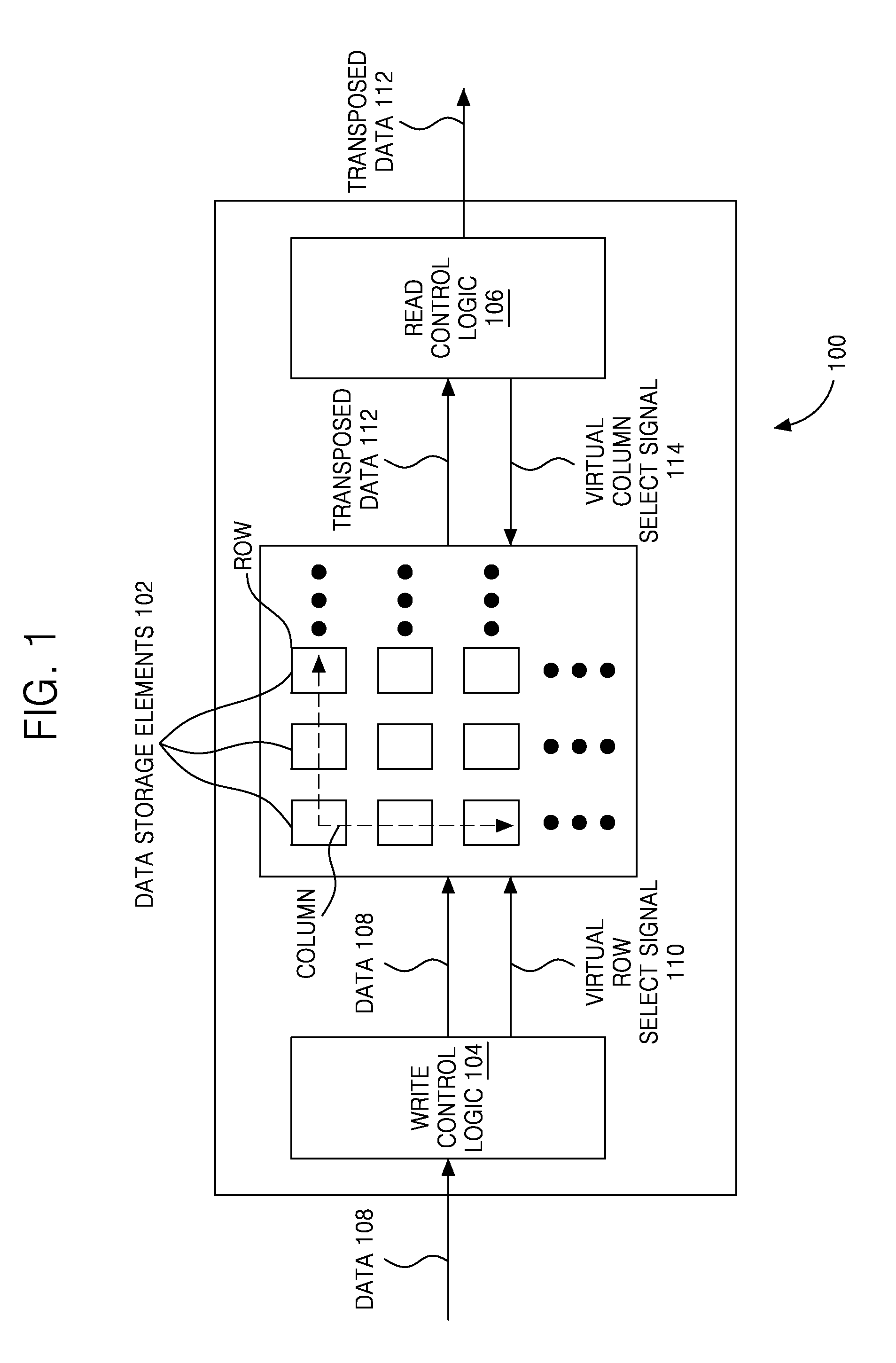
[0023]FIG. 1 illustrates a block diagram of a device 100 for successively transposing a two dimensional (2D) structure, according to an exemplary embodiment. The device 100 includes data storage elements 102, write control logic 104, and read control logic 106. The data storage elements 102 may be memory elements or registers. It will be appreciated that the data storage elements 102 may together constitute memory or a register. Each of the data storage elements 102 is configured to store a single bit or multiple bits of data (e.g., image or video data). The write control logic 104 and the read control logic 106 may include combinational logic gat...


PUM


Abstract

A system and method for successively transposing a matrix is disclosed. The device includes a plurality of data storage elements arranged as a two dimensional (2D) structure including X rows and Y columns. The device further includes write control logic coupled to the input of plurality of data storage elements for writing data in at least one virtual row. The device also includes read control logic coupled to the output of the plurality of data storage elements for reading the data from at least one virtual column, where the data write to the at least one virtual row and the data read from the at least one virtual column are performed substantially simultaneously during each cycle of operation such that the 2D structure is transposed successively with zero cycle delay between successive transposes.

Description

CROSS-REFERENCE TO RELATED PATENT APPLICATIONS[0001]This application claims priority from Indian Patent Application No. 1126 / CHE / 2010, filed on Apr. 21, 2010 in the Indian Patent Office, and from Korean Patent Application No. 10-2010-0063690, filed on Jul. 2, 2010 in the Korean Intellectual Property Office, the entire disclosures of which are incorporated herein by reference.BACKGROUND[0002]1. Field[0003]Methods and apparatuses consistent with exemplary embodiments relate to transposing matrices, and more particularly they relate to successively transposing a matrix.[0004]2. Description of the Related Art[0005]Manipulation of systems of arrays of numbers has resulted in development of various matrix operations. One such matrix operation is called the transpose which has a representation as MT, where M defines the matrix and T defines the transpose operation. Matrix transpose is a permutation frequently performed in linear algebra and particularly useful in finding the solution set f...

Claims


Application Information

Patent Timeline
Patent Type & Authority Applications(United States)
IPC IPC(8): G06F7/78G06F17/14
CPCG06F17/16G06F17/147
Inventor YAGAIN, HARISH SHRIDHAR
Owner SAMSUNG ELECTRONICS CO LTD
Why Eureka
Try Eureka