
Suspension assembly

a suspension assembly and air spring technology, applied in vehicle springs, transportation and packaging, metal-working apparatuses, etc., can solve the problems of trailing arm suspension, less than ideal suspension system, and conflicting durability with economical cost involved in achieving safety and durability

Active Publication Date: 2011-11-03
TRANSPORTATION TECH
View PDF8 Cites 5 Cited by
  • Summary
  • Abstract
  • Description
  • Claims
  • Application Information

AI Technical Summary

Problems solved by technology

Often these characteristics conflict and compete, thus necessitating a compromise of one characteristic against another characteristic, which often results in a suspension system being less than ideal.
Durability conflicts with economical cost involved in achieving safety and durability.
One type of suspension, the trailing arm suspension, has a variety of undesirable characteristics.
That is, when a vehicle's brakes are applied, the suspension will tend to compress thereby reducing the suspension's effectiveness.
Similarly, when the brakes are applied as the vehicle moves in reverse, the suspension will tend to rise up, and pivot about the single trailing arm pivot, again reducing the suspension's effectiveness.
Further, most trailing arm suspensions suffer from dock walk because they move toward or away from the loading dock as the suspension moves up or down with the brakes locked.

Method used


Image

  • Suspension assembly
  • Suspension assembly
  • Suspension assembly

Examples


Embodiment Construction

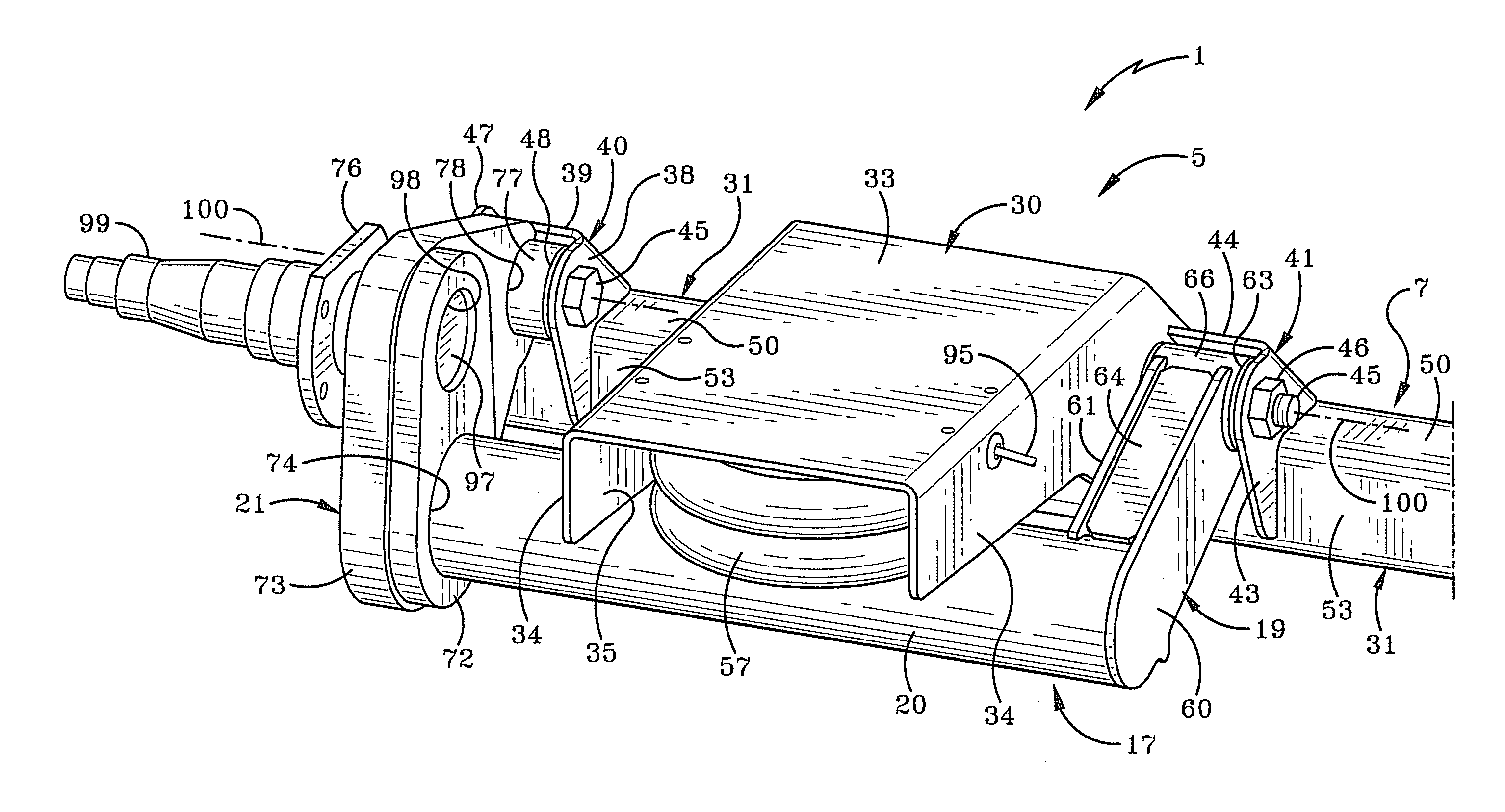
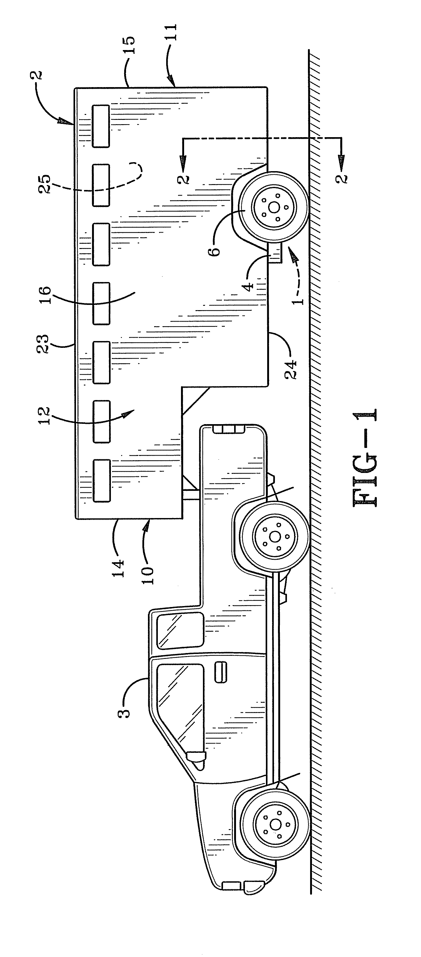
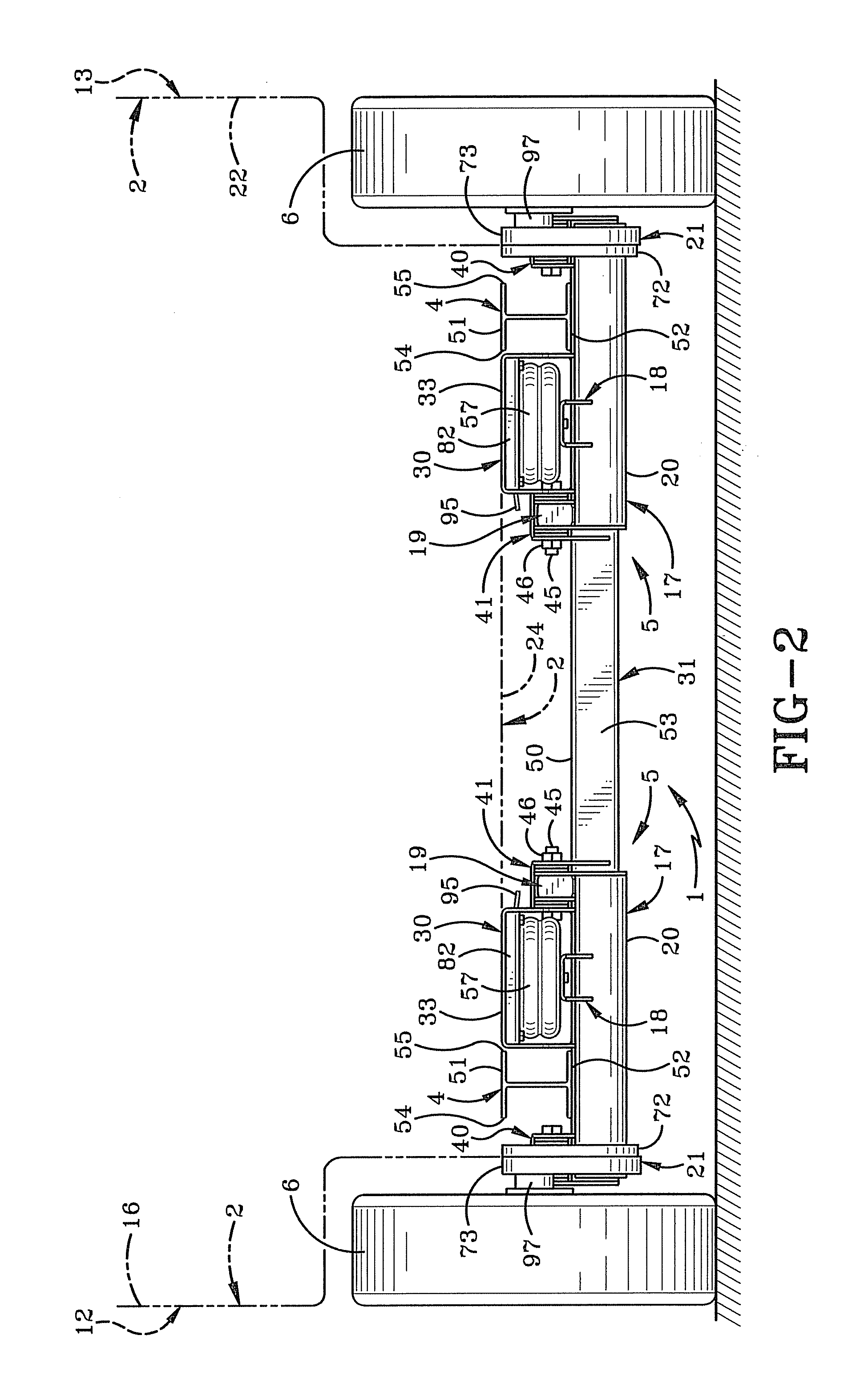
[0020]In FIG. 1, a vehicle suspension system indicated generally at 1 shown is mounted on a towed vehicle or trailer 2 being towed by a truck 3 or the towed vehicle. As shown in FIG. 2, the suspension system 1 includes a suspension assembly 5 with one suspension assembly 5 associated with each of the left and right tires 6 of the trailer 2. Wheels 6 are standard wheels each including a hub, rim mounted on the hub and a tire mounted on the rim. The suspension assemblies generally operate independent of one another. Even though two or more suspension assemblies 5 are used in a suspension system 1, this specification and figures will focus on the preferred embodiment of one suspension assembly 5 because the suspension assemblies are the same or mirror images of one another. The preferred embodiment of the suspension assembly 5 is shown in detail in FIGS. 3-11.

[0021]The trailer 2 has a front 10 and a back 11 (FIG. 1) defining therebetween a longitudinal direction, and left and right sid...


PUM

PropertyMeasurementUnit
diameteraaaaaaaaaa
center of gravityaaaaaaaaaa
durableaaaaaaaaaa

Abstract

A suspension system includes a frame mount assembly, a swing arm assembly and an air spring. The trailer includes a rail with top and bottom rail surfaces. The swing arm assembly is pivotally mounted to a pivot about a swing arm pivot axis located above the bottom rail surface when the suspension assembly is mounted to the trailer.

Description

BACKGROUND OF THE INVENTION[0001]1. Technical Field[0002]The invention relates to suspension systems for vehicles, such as trailers and trucks. More particularly, the invention relates to a suspension assembly having an air spring. Even more particularly, the invention relates to a more compact air spring suspension assembly with the air spring located between frame rails of a vehicle to provide a lower center of gravity than traditional suspension systems.[0003]2. Background Information[0004]Truck or trailer suspension systems should be as safe, durable, and as economical as possible. Often these characteristics conflict and compete, thus necessitating a compromise of one characteristic against another characteristic, which often results in a suspension system being less than ideal. For example, safety considerations dictate that the suspension be sufficiently rigid in its various planes to maintain the vehicle's line of travel. However, safety also necessitates that the suspension...

Claims


Application Information

Patent Timeline
Patent Type & Authority Applications(United States)
IPC IPC(8): B60G3/06B21D53/88
CPCB60G3/145B60G11/27B60G2200/132Y10T29/49622B60G2300/04B60G2300/042B60G2300/38B60G2202/152
Inventor VANDENBERG, ERVIN K.CROSTON, DAVID H.
Owner TRANSPORTATION TECH
Learn More