Dimmable LED Power Supply with Power Factor Control

a technology of led power supply and power factor control, which is applied in the direction of electric variable regulation, process and machine control, instruments, etc., can solve the problems of insufficient general illumination, low cost of high-power leds, and ideal led light output for indicator applications

Inactive Publication Date: 2011-11-03
INFINEON TECH AUSTRIA AG
View PDF4 Cites 63 Cited by
  • Summary
  • Abstract
  • Description
  • Claims
  • Application Information

AI Technical Summary

Benefits of technology

[0011]A dimmable LED power supply circuit arrangement is disclosed. The circuit arrangement includes: a flyback converter coupled between an input for receiving a rectified alternating line voltage and an output providing power for at least one LED device. The flyback converter includes a transformer and a semiconductor switch for switching a primary current of the transformer. A current sensing unit provides a current sense signal dependent on the primary current. A

Problems solved by technology

Traditionally, LED light output was ideal for indicator applications but insufficient for general illumination.
However, the cost of these high power LEDs continues to fall while efficiency (luminous flux generated per unit of electrical power consumed) continues to rise.
Further, LEDs are current driven rather than voltage driven devices.
Switching power conversion in the circuit design is necessary but not sufficient to satisfy the one-step conversion requirement while capitalizing on the inherent efficiency.

Method used


Image

  • Dimmable LED Power Supply with Power Factor Control
  • Dimmable LED Power Supply with Power Factor Control
  • Dimmable LED Power Supply with Power Factor Control

Examples


Embodiment Construction

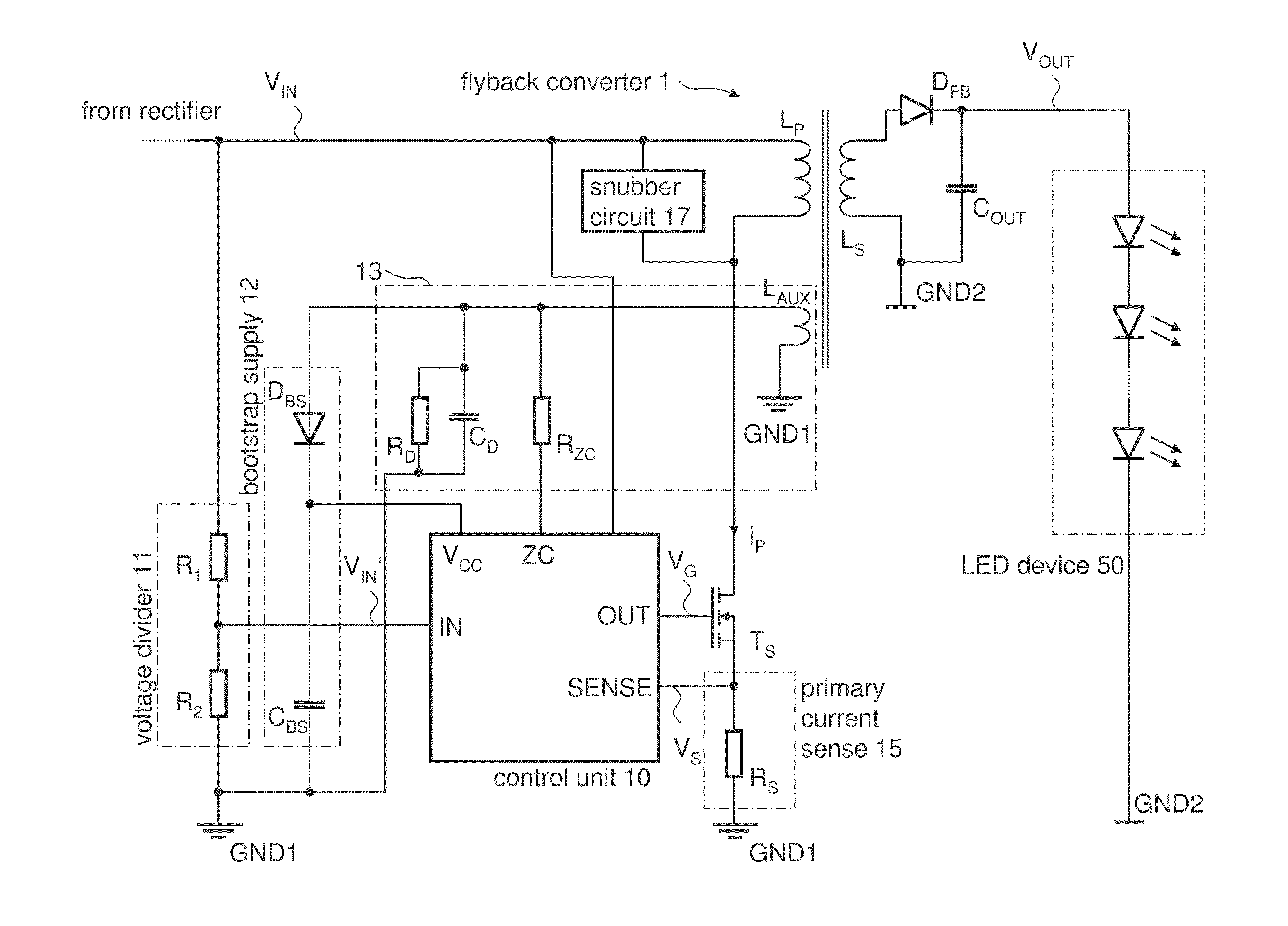
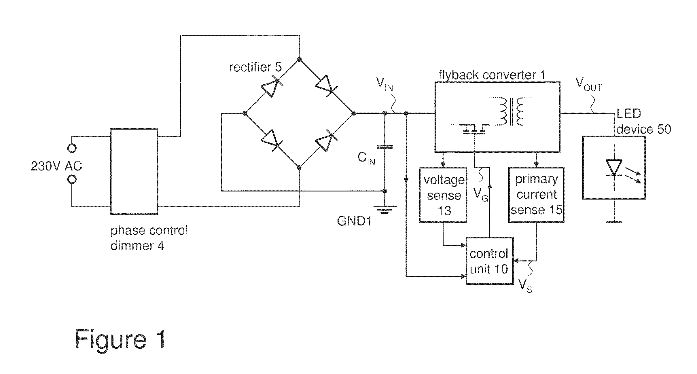
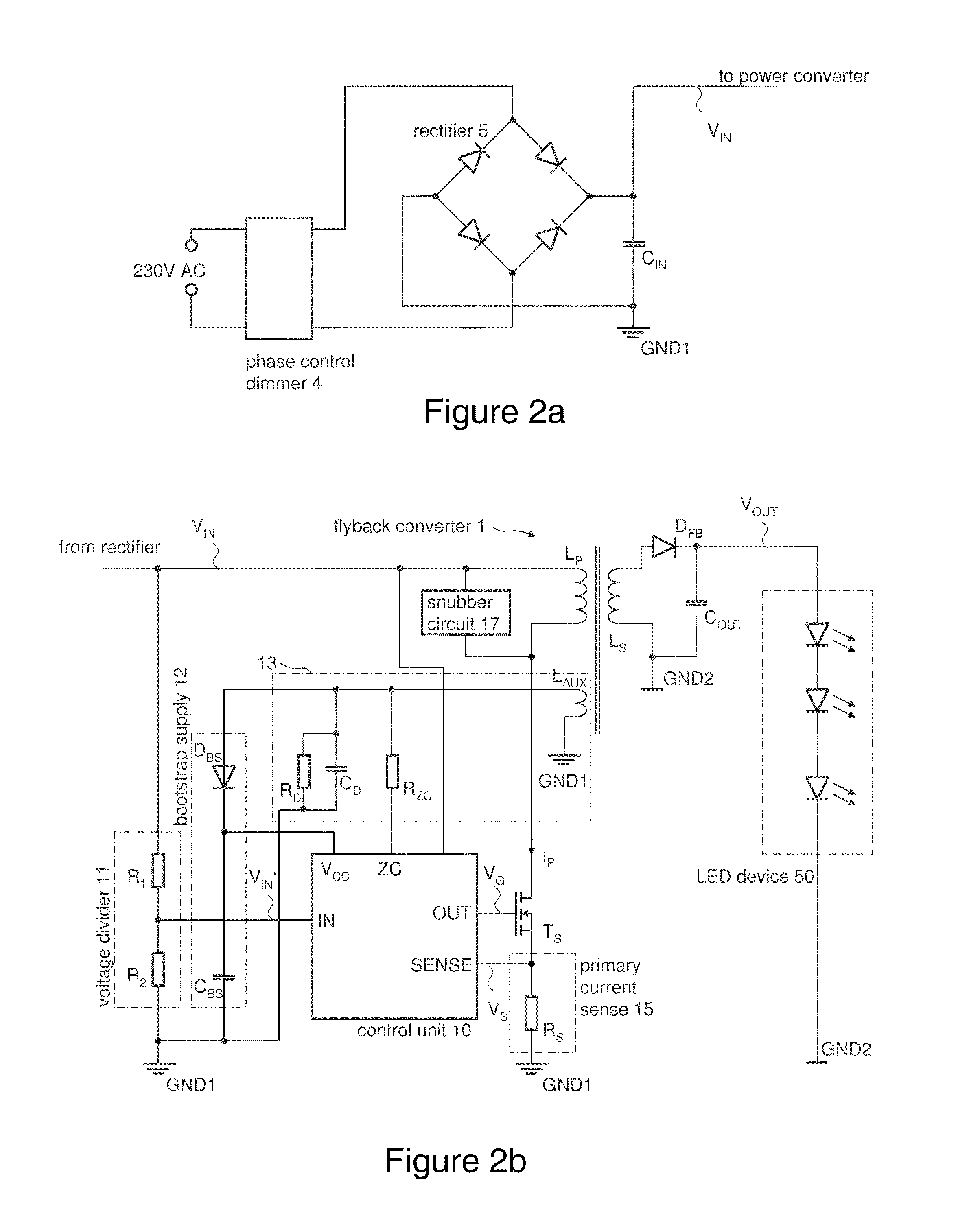
[0019]FIG. 1 illustrates the basic structure of a dimmable LED power supply circuit arrangement in accordance to one example of the present invention. The circuit arrangement comprises a flyback converter 1 which, includes a primary side and a secondary side which are galvanically isolated by a transformer, having a primary winding LP and a secondary winding LS (see also FIG. 2).

[0020]The primary winding LP of a flyback converter 1 is coupled to a rectifier 5 configured to rectify an alternating line voltage supplied by, for example, the power grid, whereby the line voltage may be subject to phasecut dimming.

[0021]The secondary winding LS of the flyback converter 1 is coupled to a load, i.e. the LED device 50, for supplying output power thereto. The flyback converter 1 further includes a power semiconductor switch T1 for controlling the current flow through the primary winding LP (denoted as primary current iP). That is, the semiconductor switch is configured to switch the primary c...


PUM


Abstract

A dimmable LED power supply circuit arrangement is disclosed. The circuit arrangement includes a flyback converter coupled between an input for receiving a rectified alternating line voltage and an output providing power for at least one LED device. The flyback converter includes a transformer and a semiconductor switch for switching a primary current of the transformer. A current sensing unit provides a current sense signal dependent on the primary current. A control unit controls the switching operation of the semiconductor switch dependent on the rectified alternating line voltage and the current sense signal such that the flyback converter operates in a quasi-resonant mode of operation, whereby the current sense signal is compared with a time-varying reference signal representing the rectified alternating line voltage and whereby a switch-off time of the semiconductor switch is determined dependent on the comparison.

Description

TECHNICAL FIELD[0001]The present disclosure relates to a switched mode power supply for efficiently driving LED devices including power factor control.BACKGROUND[0002]Since their commercial appearance in the 1960's, light emitting diodes (LED) have become ubiquitous in electronic devices. Traditionally, LED light output was ideal for indicator applications but insufficient for general illumination. However, in recent years a great advance in the development of high-intensity LEDs has occurred. These new LEDs operate at much higher current levels than their predecessors (350 milliamps to several amperes compared to the 10-50 milliamp range for traditional LEDs). These new power LEDs produce sufficient output to make them practical as sources of illumination.[0003]Presently, the high cost of the new power LEDs renders them best suited for applications where the unique characteristics of LEDs (ruggedness, long life, etc.) compensate for the extra expense. However, the cost of these hig...

Claims


Application Information

Patent Timeline
IPC IPC(8): H05B41/36H05B44/00
CPCH02M1/4258H02M3/33507Y02B70/126H05B33/0815H05B45/382H05B45/355Y02B70/10H05B45/392
Inventor LUDORF, WERNER
Owner INFINEON TECH AUSTRIA AG
Why Eureka
Try Eureka