Lighting device with adjustable light beam, particularly for a flashlight

a technology of adjustable light beams and lighting devices, which is applied in semiconductor devices, light sources, lighting and heating equipment, etc., can solve the problems of system like other similar systems, and inability to achieve satisfactory light beams. achieve the effect of simple and effective system

Active Publication Date: 2011-11-03
FRAEN CORPORATION
View PDF9 Cites 82 Cited by
  • Summary
  • Abstract
  • Description
  • Claims
  • Application Information

AI Technical Summary

Benefits of technology

[0008]The device of the invention is a simple, effective system for adjusting the width of a light beam, while being very efficient,

Problems solved by technology

This system, like other similar systems, is not free from drawbacks, however, especially if used with LED light sources.
Furthermore, satisfactory light beams are not generally o

Method used


Image

  • Lighting device with adjustable light beam, particularly for a flashlight
  • Lighting device with adjustable light beam, particularly for a flashlight
  • Lighting device with adjustable light beam, particularly for a flashlight

Examples


Embodiment Construction

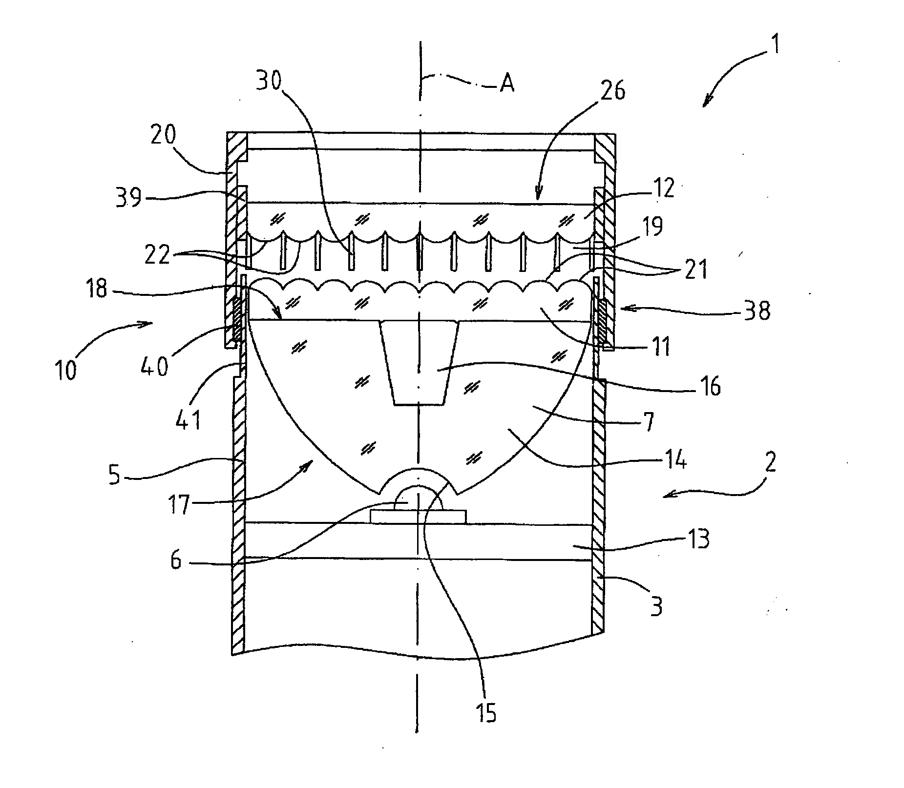
[0014]In FIG. 1, numeral 1 indicates as a whole an adjustable light beam lighting device, used for example in a flashlight 2; it is understood that the device 1 may be also applied to other types of lighting apparatuses.

[0015]The flashlight 2 comprises a tubular body 3 (only partially shown in FIG. 1) accommodating one or more batteries (not shown); an end portion of the body 3 forms a casing 5 for accommodating the device 1.

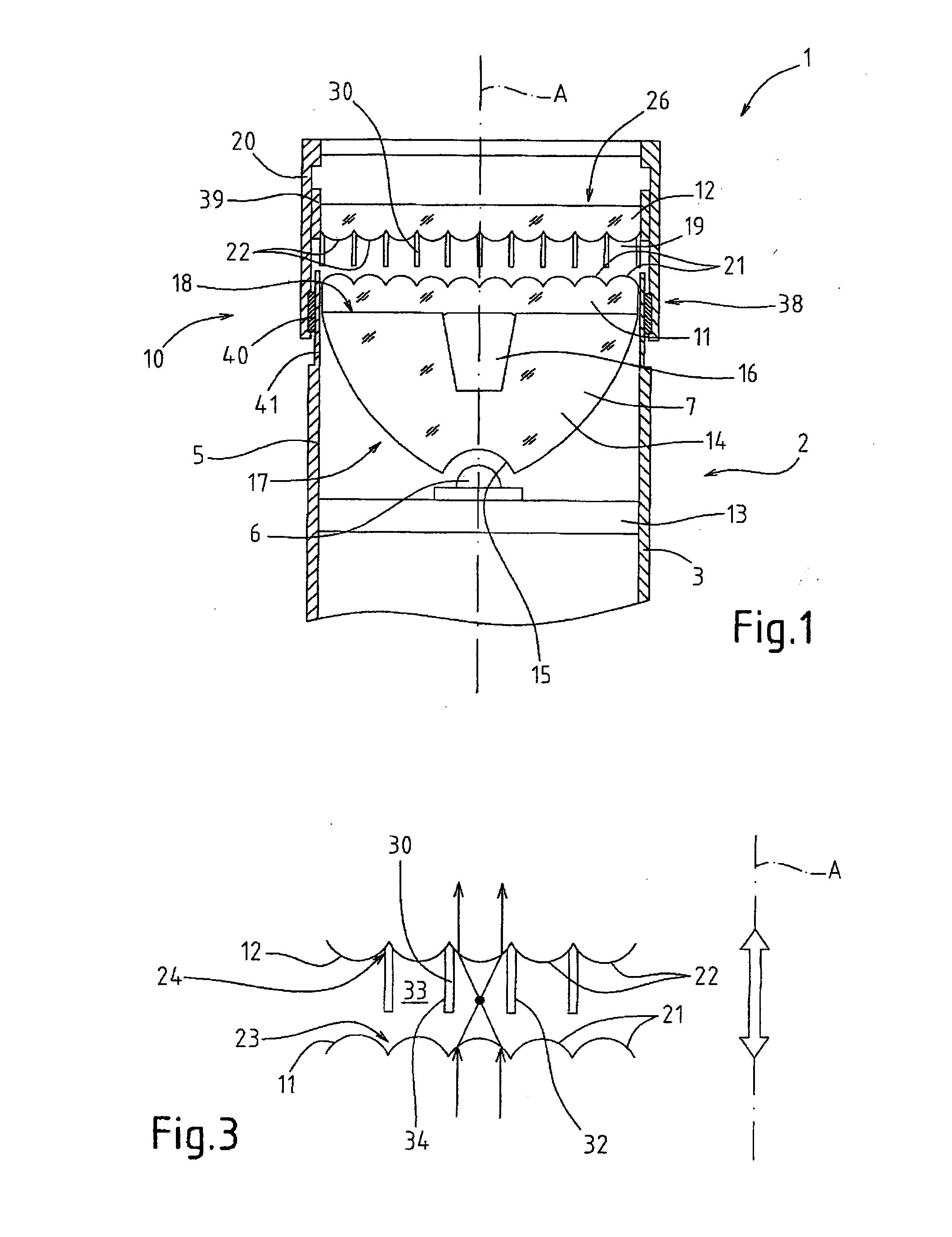
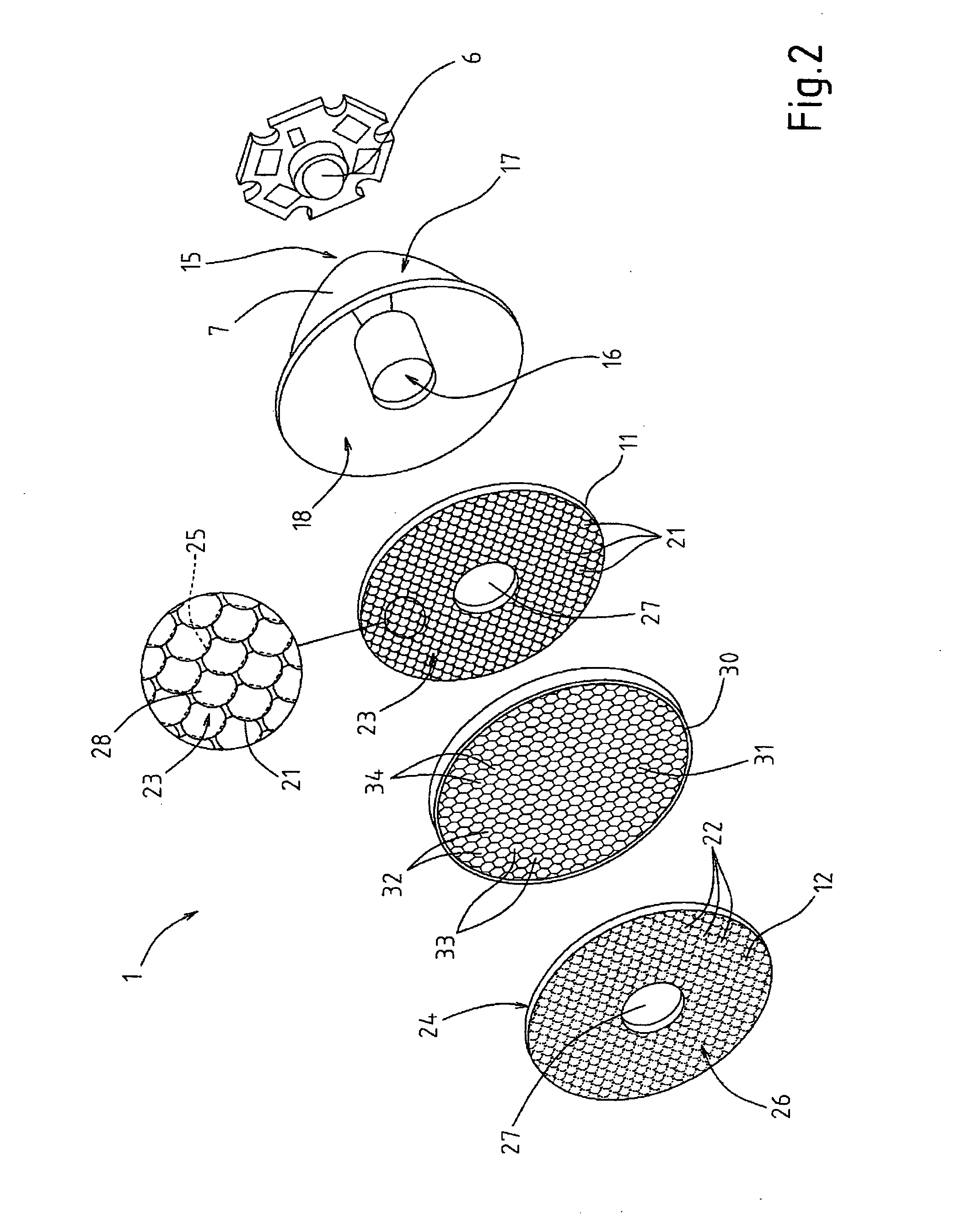
[0016]The device 1 substantially extends along an axis A and comprises in succession along axis A: a light source 6, a collimator 7 collimating the light emitted by the source 6 into a collimated beam, and a first optical element 11 and a second optical element 12 provided with respective arrays of lenses 21, 22; the device 1 further comprises a movement mechanism 10 capable of moving the elements 11, 12 with respect to each other by a movement of translation only along axis A, so as to vary the distance along axis A between the elements 11, 12 and therefore var...


PUM


Abstract

An adjustable light beam lighting device, particularly for a flashlight, has in succession along an axis a light source, a collimator collimating the light into a collimated beam, and a first optical element and a second optical element provided with respective arrays of side-by-side lenses arranged according to a network pattern. The lenses of the first element face respective lenses of the second element and are shaped to, respectively, converge and diverge the light from the collimated beam. A mask between the elements is shaped to laterally screen the light exiting from each lens of the first element and to convey the light exiting from each lens of the first element only on the facing lens of the second element, thus screening the adjacent lenses. A movement mechanism translates the elements with along the axis to vary the width of the beam emitted by the device.

Description

TECHNICAL FIELD[0001]The present invention relates to an adjustable light beam lighting device, particularly (but not only) adapted to be employed in a flashlight.BACKGROUND ART[0002]A flashlight provided with an adjustable light beam system is disclosed, for example, by WO2006072885. This system, like other similar systems, is not free from drawbacks, however, especially if used with LED light sources.[0003]In fact, using central symmetry lenses (e.g. annular lenses arranged about the optical axis of the device, as shown indeed in WO2006072885) determines the formation of light rings, instead of a homogenous light beam.[0004]Furthermore, satisfactory light beams are not generally obtained with the mentioned system (but also with other systems having different lens shape and geometry) for every beam opening condition, but only for specific beam conditions.[0005]Finally, beams in which faults appear, in particular spots which reproduce the shape of the lenses used, are normally obtai...

Claims


Application Information

Patent Timeline
IPC IPC(8): F21V14/06
CPCF21L4/027F21V5/002F21V5/04F21V7/0091F21V5/007F21V14/065F21V14/085F21Y2101/02F21V5/004F21V11/06F21Y2115/10
Inventor ANGELINI, MARCOBIGLIATI, CLAUDIA
Owner FRAEN CORPORATION
Why Eureka
Try Eureka