
Low pressure continuous dense phase convey system using a non-critical air control system

a conveying system and dense phase technology, applied in bulk conveyors, process and machine control, instruments, etc., can solve the problems of inefficiency, inefficiency, and unnecessary air production of blowers, and achieve the effect of eliminating unnecessary venting of air

Active Publication Date: 2011-11-03
SCHENCK PROCESS LLC
View PDF20 Cites 18 Cited by
  • Summary
  • Abstract
  • Description
  • Claims
  • Application Information

AI Technical Summary

Benefits of technology

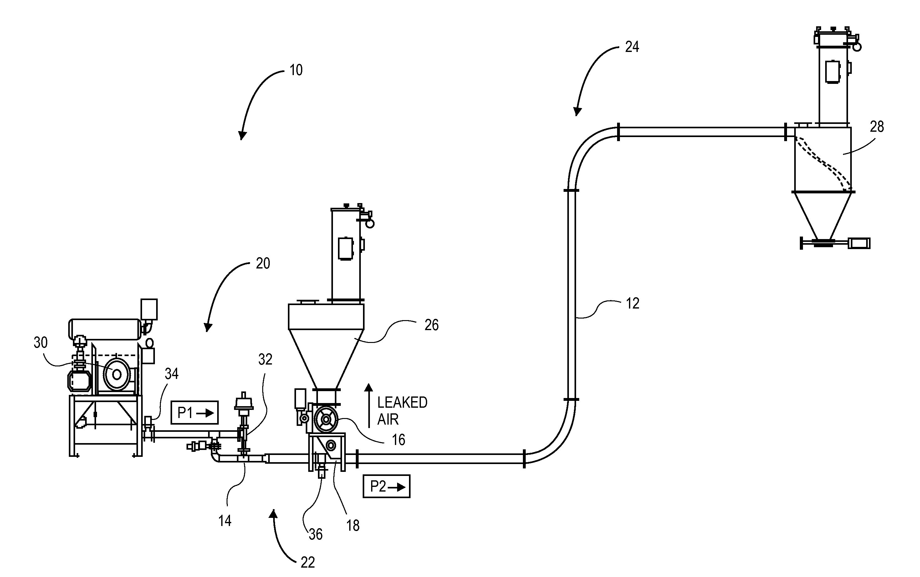
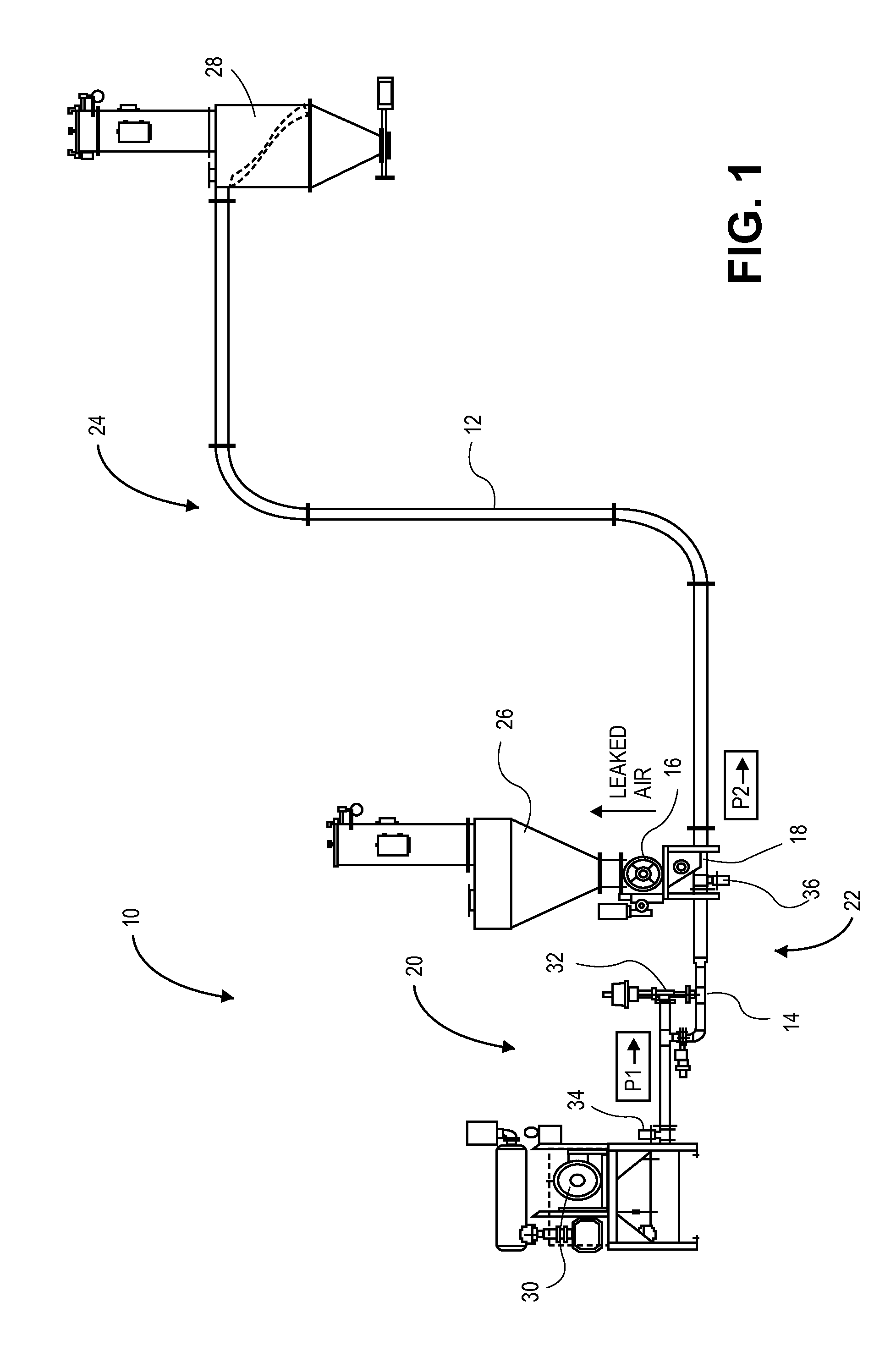
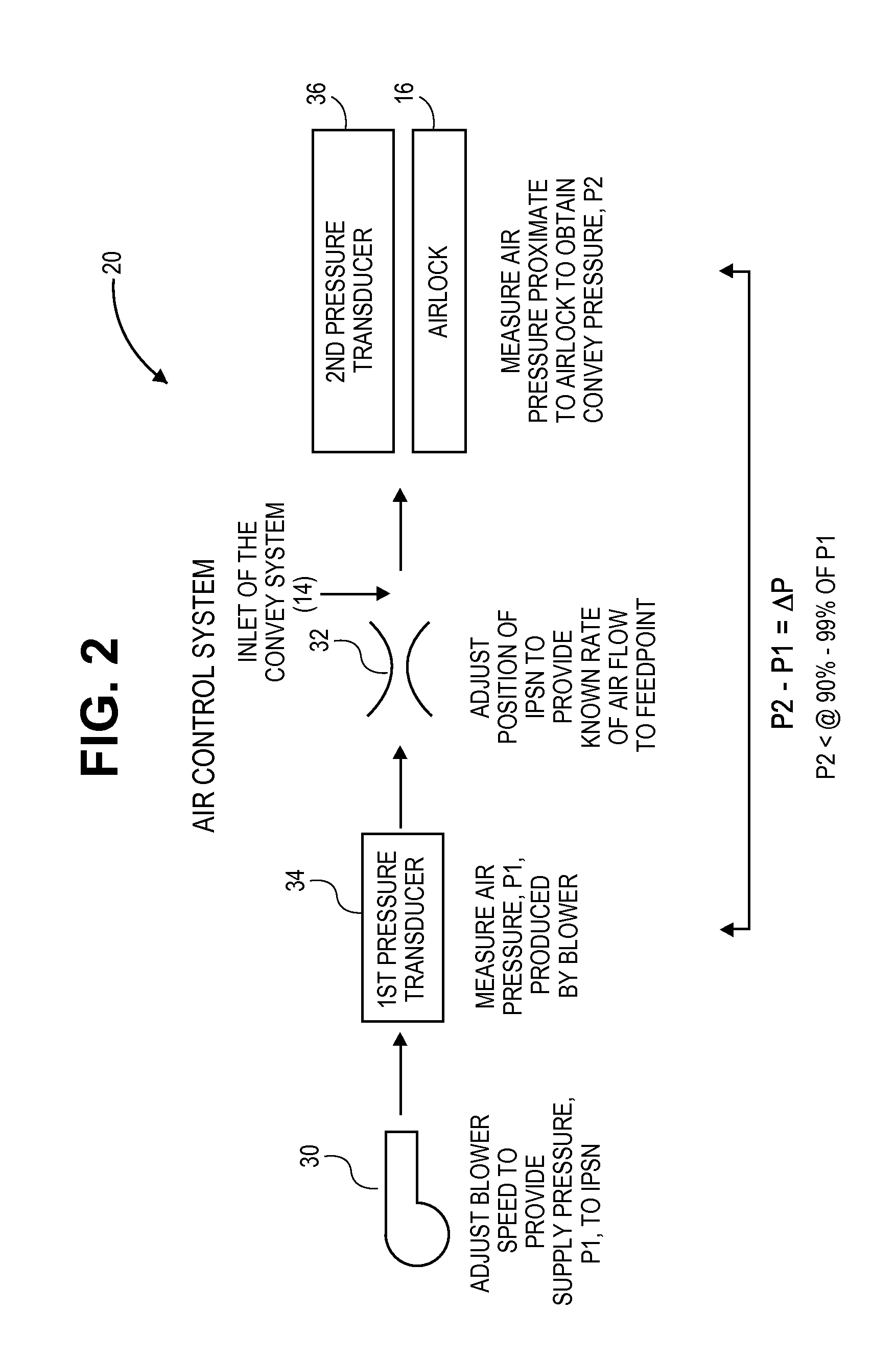
[0013]Embodiments of the present invention provide an improved air control system for a CDP convey system that addresses the above inefficiencies by eliminating the unnecessary venting of air to control the delivered air supply pressure to the feedpoint and by operating the control valve and the blower in a non-critical air flow regime. The convey system has an inlet for introduction of pressurized air into the system and an airlock associated with a feedpoint for introduction of particulate into the system. The pressurized air flows through the convey system from an upstream position and to a downstream position.

Problems solved by technology

Because the convey system pressure is constantly changing, the blower pressure is constantly throttled, resulting in inefficient and unnecessary air production by the blower.
Additionally, energy is lost to controlling the air control system accurately.
In systems where the unused air is vented to atmosphere, a varying volume of air is unnecessarily compressed, thus creating further inefficiency.
In the second prior art system described above, the unnecessary throttling of the blower inlet also produces inefficiency in energy consumption.
Prior art air control systems thus essentially overcompensate for the air supply pressure required to operate the convey system properly with the negative consequence of increased energy consumption.

Method used


Image

  • Low pressure continuous dense phase convey system using a non-critical air control system
  • Low pressure continuous dense phase convey system using a non-critical air control system
  • Low pressure continuous dense phase convey system using a non-critical air control system

Examples


Embodiment Construction

[0022]The following detailed description references the accompanying drawings that illustrate specific embodiments in which the invention can be practiced. The embodiments are intended to describe aspects of the invention in sufficient detail to enable those skilled in the art to practice the invention. Other embodiments can be utilized and changes can be made without departing from the scope of the present invention. The following detailed description is, therefore, not to be taken in a limiting sense. The scope of the present invention is defined only by the appended claims, along with the full scope of equivalents to which such claims are entitled.

[0023]In this description, references to “one embodiment,”“an embodiment,” or “embodiments” mean that the feature or features being referred to are included in at least one embodiment of the technology. Separate references to “one embodiment,”“an embodiment,” or “embodiments” in this description do not necessarily refer to the same embo...


PUM


Abstract

An air control system for a low pressure continuous dense phase convey system employs a non-critical air flow control system that allows for a supply pressure to be only incrementally larger than a convey pressure. The convey system has an inlet for introduction of pressurized air into the system and an airlock associated with a feedpoint for introduction of particulate into the system. A first pressure sensor is positioned immediately downstream of an air source to measure the supply pressure, and a second pressure transducer is positioned proximate an airlock to measure the convey pressure. The non-critical air flow control system is dependent on the supply and convey pressures and a position of a control valve, such as a sonic nozzle. The difference between the convey pressure and the supply pressure is less than 10% of the supply pressure.

Description

RELATED APPLICATION[0001]The present non-provisional patent application claims priority benefit, with regard to all common subject matter, of U.S. Provisional Patent Application No. 61 / 330,677, filed May 3, 2010, and entitled “Low Pressure Continuous Dense Phase Convey System Using a Non-Critical Air Control System.” The above-referenced provisional patent application is hereby incorporated by reference in its entirety.BACKGROUND[0002]1. Field[0003]Embodiments of the present invention relate to continuous dense phase pneumatic convey systems. More particularly, embodiments of the present invention relate to a low pressure continuous dense phase convey system that employs a non-critical air control system so as to achieve relatively low energy consumption while maintaining minimal particulate degradation.[0004]2. Related Art[0005]A low pressure continuous dense phase (“LPCDP” or “CDP”) convey system uses a low pressure air supply to drive a low effective air velocity (approximately 4...

Claims


Application Information

Patent Timeline
Patent Type & Authority Applications(United States)
IPC IPC(8): B65G53/46B65G53/66
CPCB65G53/66G05D7/0688
Inventor THORN, JONATHAN
Owner SCHENCK PROCESS LLC
Learn More