Orthotic

a technology of orthotics and spondylitis, applied in the field of orthotics, can solve the problems of large patient power, inability to provide simultaneous freedom of all movements, and inability to obtain correct corrections for patients

Inactive Publication Date: 2011-11-03
IND TECH RES INST
View PDF1 Cites 6 Cited by
  • Summary
  • Abstract
  • Description
  • Claims
  • Application Information

AI Technical Summary

Benefits of technology

[0006]The disclosure is directed to an orthotic for correcting a movement of a hip joint. The orthotic can simultaneously provide the degrees of freedom of the movements of flexion, extension, adduction and abduction in the walking friction of the patient so that the patient can obtain opportune correcting procedure closer to the normal gait curve.
[0007]According to the present disclosure, an orthotic for correcting a movement of a hip joint of a user is provided. The orthotic includes a support frame, a cam, a leg fixer, a following element and a restoring element. The support frame is attached to the user. The cam is disposed to the support frame. The leg fixer is pivotally connected to the support frame. The following element is moveably mounted on the leg fixer and contacted to the cam. The restoring element connected to the leg fixer provides a force of restoring the leg fixer when the leg fixer is moved. When the leg fixer is being moved, a predetermined relative movement between the cam and the following element is generated to correct a movement range of the hip joint.

Problems solved by technology

The above-mentioned hinge mechanism only provides the degrees of freedom of some of the movements of flexion, extension, adduction and abduction, but cannot simultaneously provide the degrees of freedom of all the movements of flexion, extension, adduction and abduction.
Thus, the patient cannot obtain the correct correction.
In this case, the power of the patient is also consumed when the patient uses the conventional orthotic for a long time, thereby causing the great loading on the power of the patient.

Method used


Image

  • Orthotic
  • Orthotic
  • Orthotic

Examples


Embodiment Construction

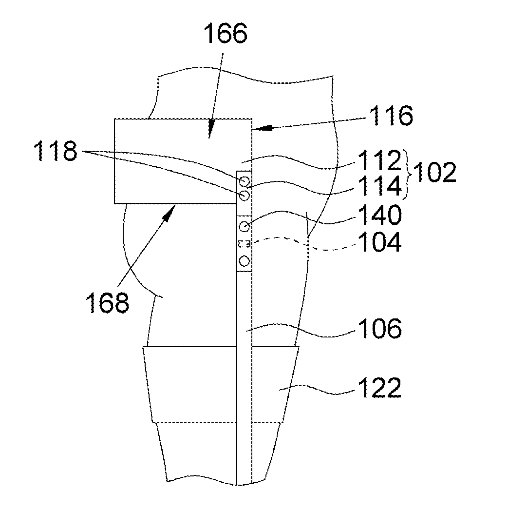
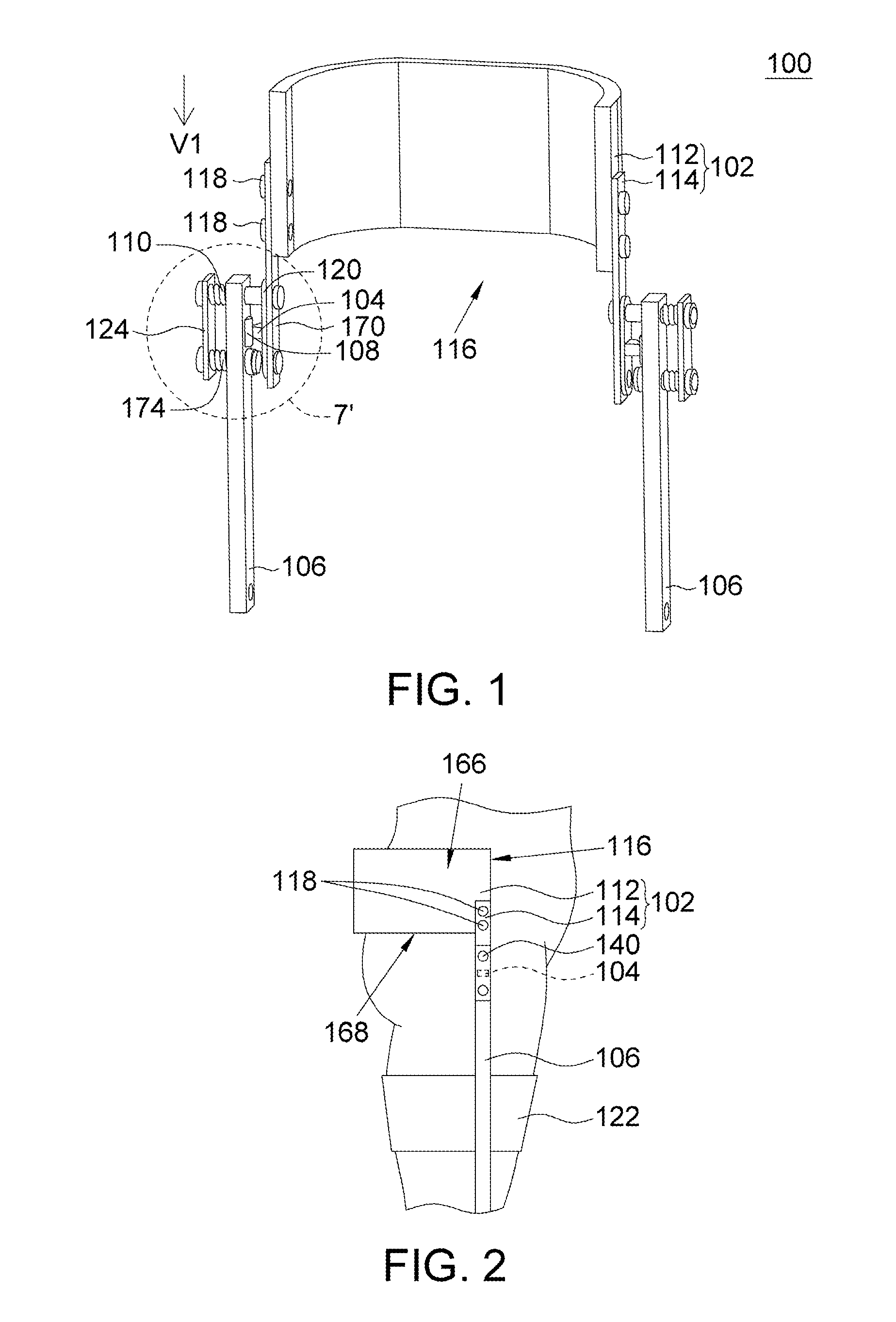
[0020]FIG. 1 is an assembled view showing an orthotic 100 according to a preferred embodiment of the disclosure. Referring to FIG. 1, the orthotic 100 for correcting a movement of a hip joint of a user includes a support frame 102 and two assistive correcting mechanisms. The assistive correcting mechanisms are symmetrically disposed on two sides of the support frame 102. Each assistive correcting mechanism includes a cam 104, a leg fixer 106, a following element 108, a pressing plate 124 and restoring elements 110 and 174. The restoring elements 110 and 174 are springs, for example. The following element 108 is a roller, for example. The cam 104 and the following element 108 constitute a cam movement mechanism. However, this does not intend to restrict the disclosure. In other aspects, the following element 108 may also be a ball, a roller or any other following element, which can form a kinematic pair together with the cam 104.

[0021]FIG. 2 is a schematic illustration showing the or...


PUM


Abstract

An orthotic for correcting a movement of a hip joint of a user includes a support frame, a cam, a leg fixer, a following element and a restoring element. The support frame is attached to the user. The cam is disposed to the support frame. The leg fixer is pivotally connected to the support frame. The following element is moveably mounted on the leg fixer and connected to the cam. The restoring element connected to the leg fixer provides a force of restoring the leg fixer when the leg fixer is moved. When the leg fixer is being moved, a predetermined relative movement between the cam and the following element is produced to correct a movement range of the hip joint.

Description

BACKGROUND OF THE DISCLOSURE[0001]1. Field of the Disclosure[0002]The disclosure relates in general to an orthotic, and more particularly to an orthotic having a cam.[0003]2. Description of the Related Art[0004]A conventional orthotic for correcting a movement of a hip joint mainly includes a hinge mechanism, which can restrict the movement of the hip joint of the human body so that the hip joint only can perform the flexion / extension movement and is not allowed to perform the adduction / abduction movement.[0005]However, a normal gait curve simultaneously includes movements of flexion, extension, abduction and adduction. The above-mentioned hinge mechanism only provides the degrees of freedom of some of the movements of flexion, extension, adduction and abduction, but cannot simultaneously provide the degrees of freedom of all the movements of flexion, extension, adduction and abduction. Thus, the patient cannot obtain the correct correction. In this case, the power of the patient is...

Claims


Application Information

Patent Timeline
Patent Type & Authority Applications(United States)
IPC IPC(8): A61F5/00
CPCA61F5/0193
Inventor CHANG, LIANG-WEYYAO, SHUN-YIHO, HUI-CHUNYANG, YEE-PIEN
Owner IND TECH RES INST
Why Eureka
Try Eureka