Rotation transmission device

Inactive Publication Date: 2011-11-10
NTN CORP
View PDF5 Cites 11 Cited by
  • Summary
  • Abstract
  • Description
  • Claims
  • Application Information

AI Technical Summary

Benefits of technology

[0028]With the rotation transmission device according to the present invention, particularly the above-mentioned first and second means, using the two one-way clutches, it is possible to rotate the output shaft always in one direction irrespective of whether the input shaft is rotating in the normal direction or the reverse direction. Thus the rotation transmission device of the invention is made up of a smaller number of parts than conventional devices, which use three one-way clutches. Further it is possible to minimize problems resulting from misalignment of the clutches, which makes it possible to more stably transmit rotation.
[0029]With the

Problems solved by technology

But since the rotation transmission device disclosed in Patent document 1 includes three one-way clutches, a large number of parts are necessary.
Also, during operation, the clutches tend to become out of alignment with each other, which causes uneven transmission of torque

Method used


Image

  • Rotation transmission device
  • Rotation transmission device
  • Rotation transmission device

Examples


first embodiment

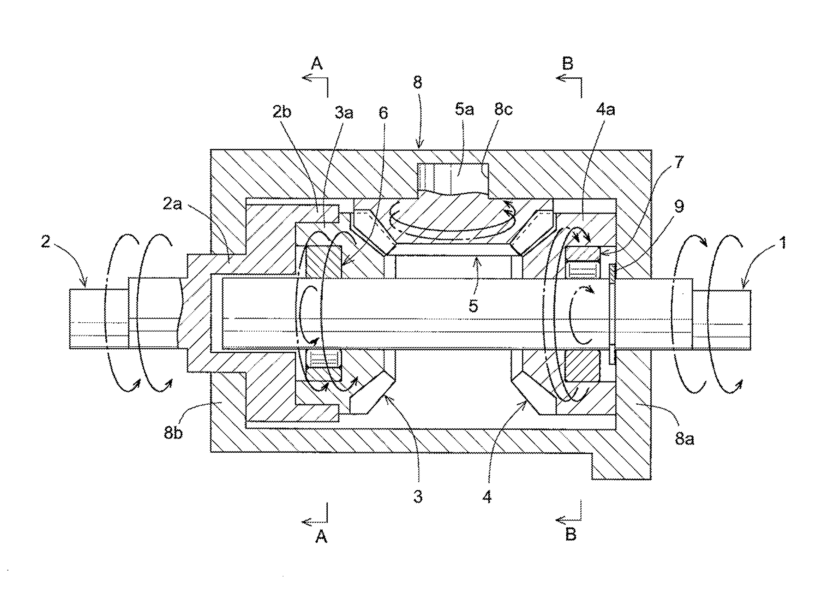
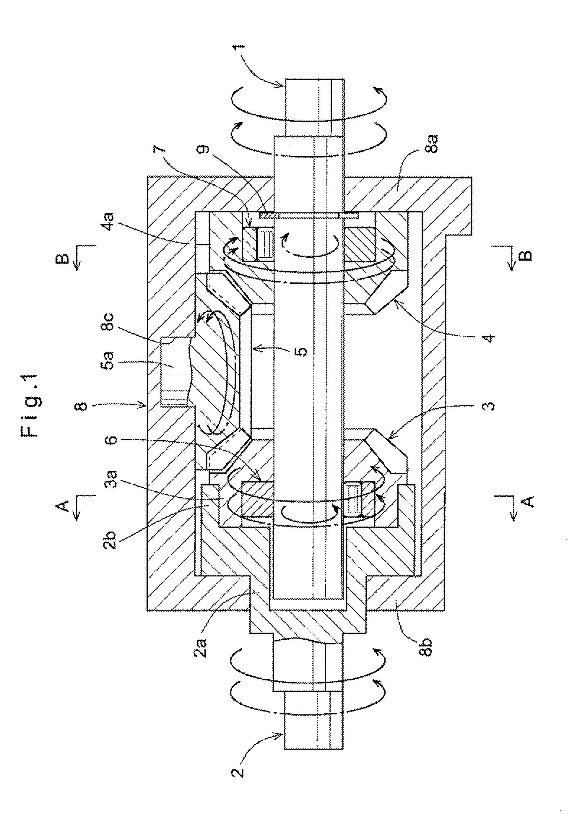
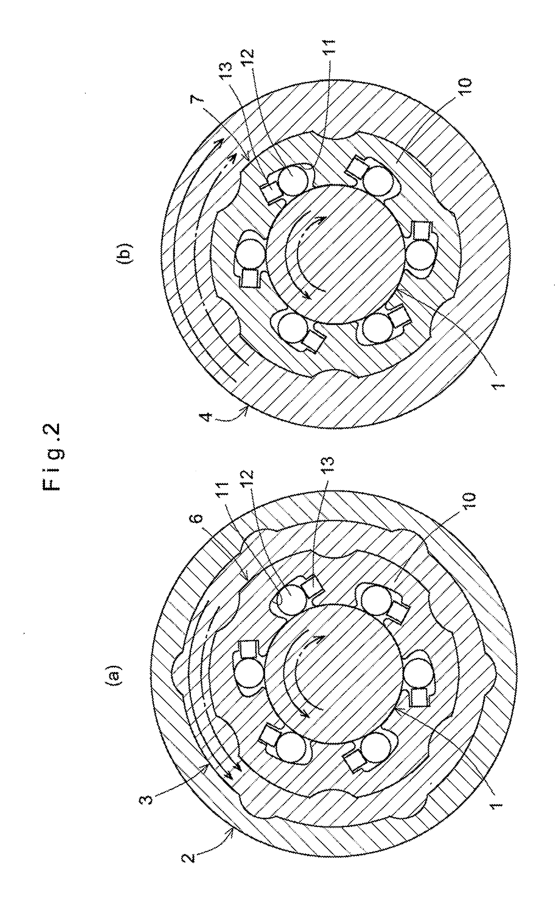
[0048]Now the embodiments are described with reference to the drawings. FIGS. 1 and 2 show the As shown in FIG. 1, the rotation transmission device of this embodiment comprises input and output shafts 1 and 2 which are coaxial with each other, a pair of opposed bevel gears 3 and 4 rotatably mounted around the input shaft 1, an intermediate bevel gear 5 meshing with both bevel gears 3 and 4, a first one-way clutch 6 disposed between the input shaft 1 and one of the opposed bevel gears on the input side, i.e. bevel gear 3, and a second one-way clutch 7 disposed between the input shaft 1 and the other of the opposed bevel gears (on the output side), i.e. bevel gear 4. The input shaft 1 and the output shaft 2 are rotatably supported by inner surfaces of through holes formed in end walls 8a and 8b of a tubular casing 8, respectively. The intermediate bevel gear 5 has a shaft portion 5a rotatably fitted in a circular hole 8c formed in the inner surface of the casing 8. While not shown, t...

seventh embodiment

[0075]FIGS. 15 and 16 show the The rotation transmission device of this embodiment is mounted in business machines such as copiers and printers, and as shown in FIG. 15, basically comprises a fixed shaft 32, and a first input member 33, a second input member 34 and an output member 35 that are arranged around the fixed shaft 32. Snap rings 36 are fitted at both end portions of the fixed shaft 32 to prevent separation of the members 33, 34 and 35, which are provided around the fixed shaft 32.

[0076]The second input member 34 has a boss portion 37 rotatably fitted around the fixed shaft 32. The boss portion 37 has integral intermediate shafts 38 at its longitudinal central portion to extend perpendicular to the fixed shaft 32. The first input member 33 and the output member 35 are rotatably mounted around the boss portion 37 with the intermediate shaft 38 disposed between the first input member 33 and the output member 35.

[0077]The first input member 33 and the output member 35 carry ...


PUM


Abstract

A rotation transmission device is provided which is simple in structure and which can stably transmit rotation. It includes input and output shafts (1 and 2) which are coaxial with each other, a pair of opposed bevel gears (3 and 4) rotatably mounted around the input shaft (1), and an intermediate bevel gear (5) meshing with the opposed bevel gears (3 and 4). The output shaft (2) and one of the opposed bevel gears (3) are rotationally fixed to each other. A first one-way clutch (6) is provided through which the rotation of the input shaft (1) is transmitted to the one of the opposed bevel gears (3). A second one-way clutch (7) is provided through which the rotation of the input shaft (1) in the reverse direction is transmitted to the other of the opposed bevel gears (4). Thus, the output shaft (2) can be rotated in the normal direction irrespective of whether the input shaft (1) is rotated in the normal direction or in the reverse direction. This device is made up of a smaller number of parts than conventional devices including three one-way clutches and is less likely to suffer from problems resulting from misalignment of the clutches during rotation.

Description

TECHNICAL FIELD[0001]The present invention relates to a rotation transmission device which can convert rotation applied to an input shaft in either direction to rotation of an output shaft in a single direction, or which can switch the rotational direction of an output member without changing the rotational direction of an input member.BACKGROUD ART[0002]It is required for some driving units of e.g. copying machines that the output shaft be always rotated in the same one direction, irrespective of whether the input shaft is rotated in one or the other direction by a rotary driving source or a reciprocating driving source. Some driving units of this type use a rotation transmission device to achieve this purpose, i.e. to convert rotation in either direction applied to the input shaft from a driving source to the rotation of the output shaft in a single direction.[0003]FIGS. 13 and 14 show a conventional rotation transmission device of this type (which is disclosed in Patent document ...

Claims


Application Information

Patent Timeline
IPC IPC(8): F16H3/02
CPCF16D41/066F16D47/04Y10T74/19172F16H31/001F16H3/003
Inventor TAKADA, SEIICHIMAIWA, TSUTOMU
Owner NTN CORP
Why Eureka
Try Eureka