Braking apparatus for vehicle

a technology for braking apparatus and vehicles, applied in the direction of braking systems, electric devices, transportation and packaging, etc., can solve the problem of reducing the friction coefficien

Inactive Publication Date: 2011-11-10
TOYOTA JIDOSHA KK
View PDF6 Cites 19 Cited by
  • Summary
  • Abstract
  • Description
  • Claims
  • Application Information

AI Technical Summary

Benefits of technology

[0010]Accordingly, in the case where friction heat; i.e., thermal energy, which is generated as a result of operation of the vehicular braking apparatus is collected and converted to, for example, electric energy by use of a thermoelectric conversion element (heat collection means), it is very important to satisfy a conflicting requirement of improving the thermal energy collection efficiency of the heat collection means without decreasing the braking force of the vehicular braking apparatus.
[0039]By virtue of this configuration, the thermal energy (friction heat) generated as a result of application of frictional braking force by the first braking force application means can be collected and converted to electric energy. By means of storing the collected electric energy in the form of, for example, electric power, the collected electric energy can be supplied to equipment mounted on the vehicle so as to operate the equipment. Accordingly, the thermal energy generated as a result of braking can be used effectively without wasting it.

Problems solved by technology

However, a braking apparatus of a vehicle (hereinafter may be referred to as a “vehicular braking apparatus”) has a limit operation temperature under which the braking apparatus can generate proper braking force at all times. That is, the vehicular braking apparatus has a characteristic such that, when the temperature of a friction portion increases, its friction coefficient decreases.

Method used


Image

  • Braking apparatus for vehicle
  • Braking apparatus for vehicle
  • Braking apparatus for vehicle

Examples


first embodiment

a. First Embodiment

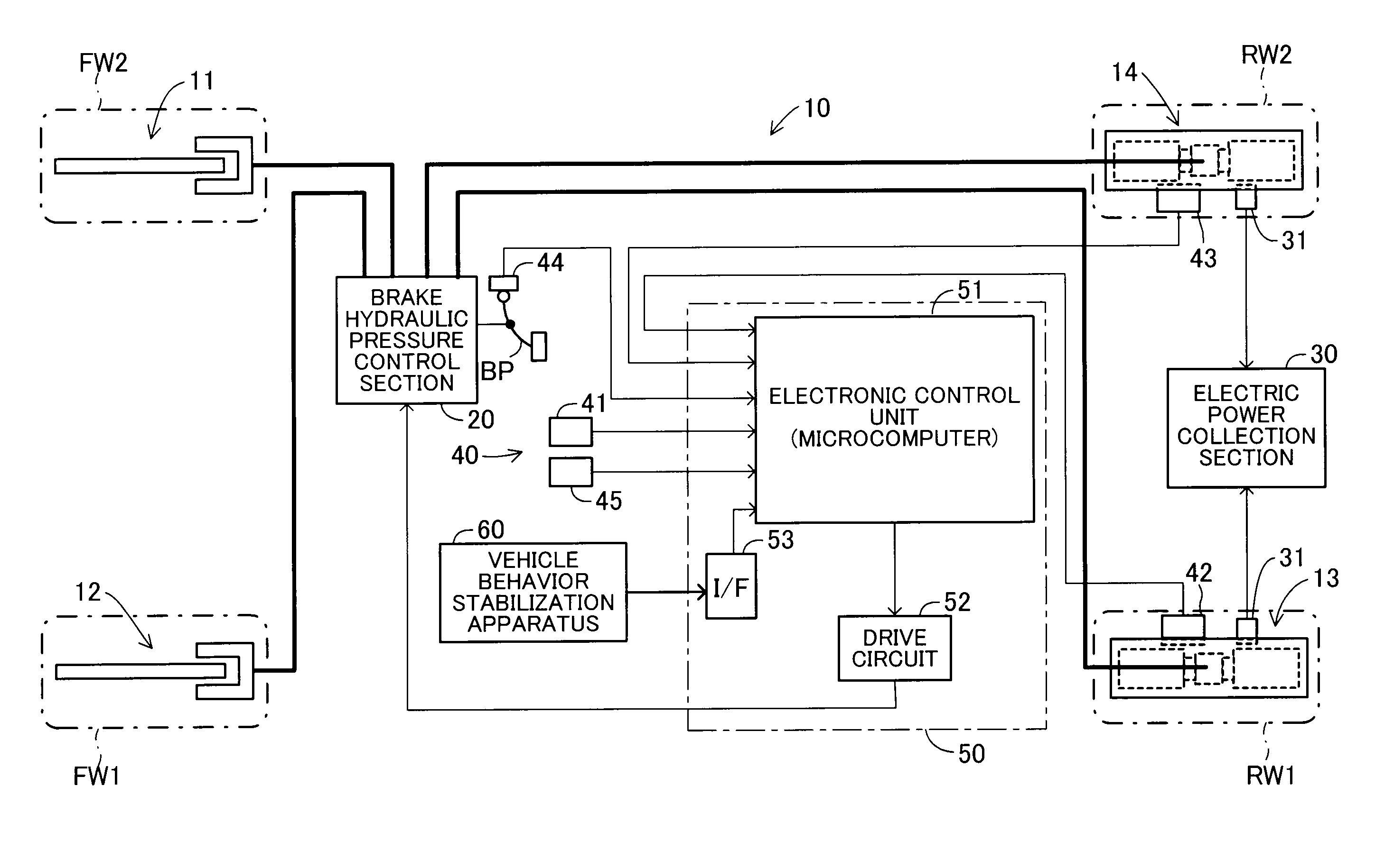
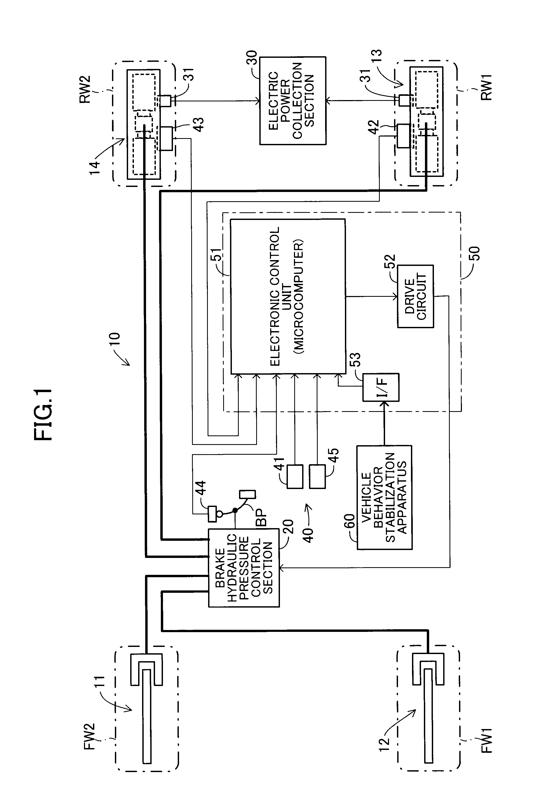
[0057]Vehicular braking apparatuses according to various embodiments of the present invention will now be described in detail with reference to the drawings. FIG. 1 schematically shows the configuration of a vehicle on which a vehicular braking apparatus 10 which is common between first and second embodiments of the present invention is mounted.

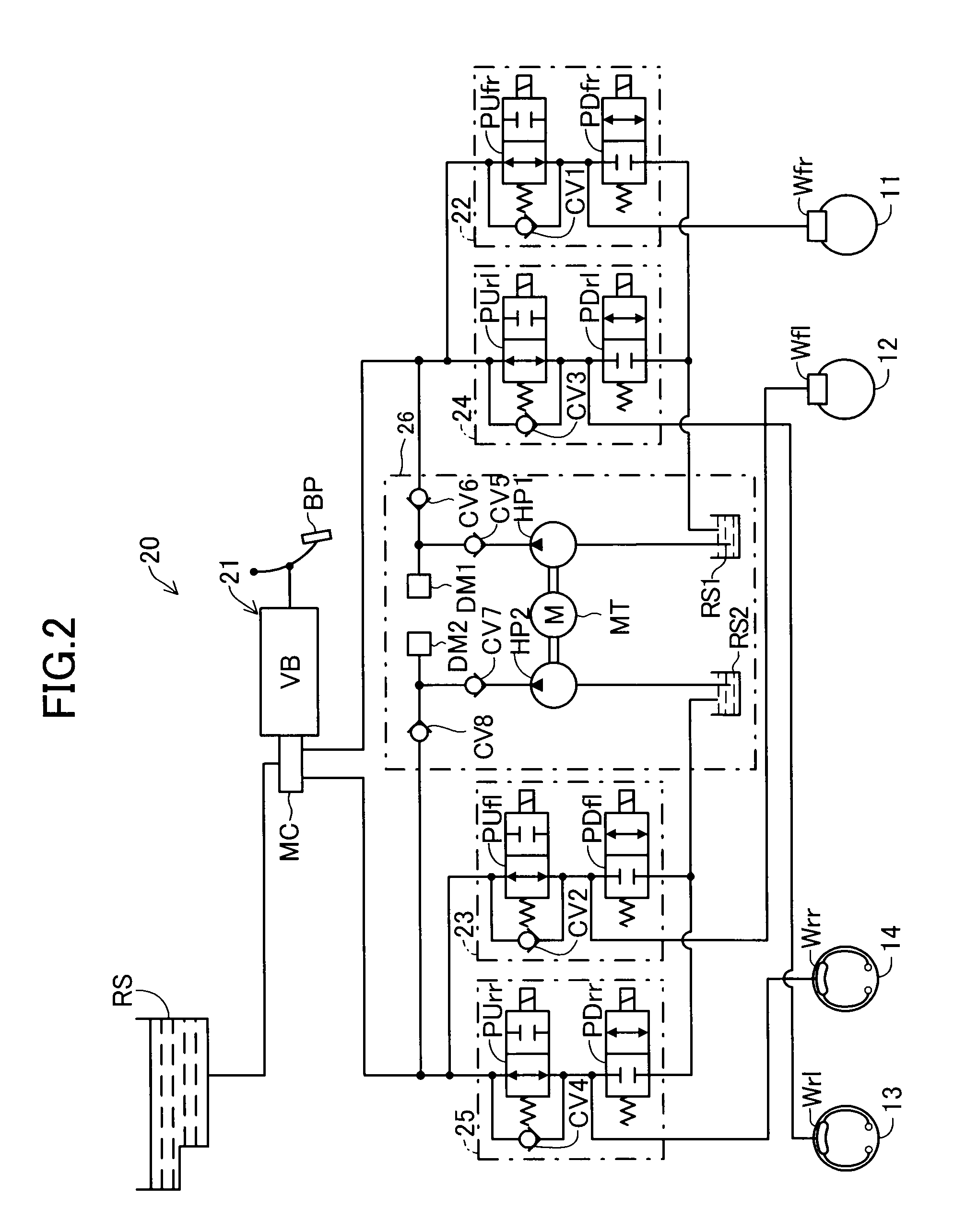
[0058]The braking apparatus 10 includes brake units 11, 12 which apply braking forces against rotations of left and right front wheels FW1, FW2 and which are excellent in cooling, and brake units 13, 14 which apply braking forces to rotations of left and right rear wheels RW1, RW2 and which are excellent in heat retention. Although not illustrated in detail in FIG. 2, the brake units 11, 12 are disc brake units. The disc brake units include brake discs which rotate together with the left and right front wheels FW1, FW2, and calipers which are fixed to, for example, front axles and have wheel cylinders Wfr, Wfl. Brake pads f...

second embodiment

b. Second Embodiment

[0110]In the above-described first embodiment, the present invention is embodied in such a manner that, when the internal space temperatures T of the brake units 13, 14 provided for the left and right rear wheels RW1, RW2 are lower than the predetermined temperature (reference temperature) Ts, which is set to coincide with the lower limit temperature of the optimum temperature range, the first braking force map shown in FIG. 6 is employed so as to operate the brake units 13, 14 preferentially, to thereby cause the internal space temperatures T to quickly exceed the predetermined temperature Ts. However, the present invention may be embodied as follows. On the basis of the dimensionless performance index shown in FIG. 4, the upper limit temperature of the optimum temperature range may be set as a previously set, predetermined temperature Tu; and, when the internal space temperatures T of the brake units 13, 14 exceed this predetermined temperature Tu, the brake un...

third embodiment

d. Third Embodiment

[0164]In the above-described embodiments and modifications, the present invention is embodied such that the brake units 11 to 18 provided for the left and right front wheels FW1, FW2 and the left and right rear wheels RW1, RW2 produce frictional braking forces; and the heating side of each thermoelectric conversion section 31 is heated, for example, within the optimum temperature range by using friction heat generated at the time of braking, so as to convert thermal energy to electric energy at a satisfactory conversion efficiency, to thereby generate regenerative electric power.

[0165]In this case, the brake units each including a thermoelectric conversion section 31 (first braking force application means) are not limited to those disposed near the wheels, and may be disposed at any location, so long as a brake unit(s) can apply braking forces to the wheels. In the below description, a third embodiment in which a brake unit including a thermoelectric conversion se...


PUM


Abstract

An electronic control unit inputs from temperature sensors a temperature of the heating side of a thermoelectric conversion section assembled to each of brake units provided for left and right rear wheels. When the temperature of the heating side is equal to or lower than a predetermined temperature, the electronic control unit drives and controls a brake hydraulic pressure control section so as to operate the brake units preferentially over brake units provided for left and right front wheels. With this operation, each of the brake units generates friction heat, and heats the heating side of the corresponding thermoelectric conversion section, whereby the thermoelectric conversion section efficiently collects thermal energy and generates electrical power. Meanwhile, when the heating side temperature is higher than the predetermined temperature, the electronic control unit drives and controls the brake hydraulic pressure control section so as to decrease the proportion of the braking forces applied by the brake units and increase the proportion of the braking forces applied by the brake units.

Description

TECHNICAL FIELD[0001]The present invention relates to a braking apparatus for a vehicle such as an automobile, and more particularly to a braking apparatus for a vehicle which brakes wheels of the vehicle and which also collects thermal energy generated as a result of braking.BACKGROUND ART[0002]In recent years, active studies have been carried out on a technique of collecting thermal energy generated as a result of traveling of a vehicle, and converting the collected thermal energy to, for example, electric energy for effective use.[0003]For example, Japanese Patent Application Laid-Open (kokai) No. H11-220804 shows a regeneration brake apparatus comprising a brake caliper which presses a brake pad against a rotation portion to thereby effect braking, a heat pipe connected to the brake caliper, a thermoelectric conversion element connected to a heart radiation end of the heat pipe, a radiator connected to a cooling side surface of the thermoelectric conversion element, and a batter...

Claims


Application Information

Patent Timeline
Patent Type & Authority Applications(United States)
IPC IPC(8): B60T7/00F16D65/16B60L50/16
CPCB60T1/10Y02T10/70B60T8/1766B60T8/267B60T13/586B60T17/22B60L3/0061B60L7/26B60L11/14B60L2210/10B60L2220/44B60L2240/12B60L2240/36B60L2240/445B60L2250/26B60L2200/26B60T2250/00Y02T10/7077Y02T10/7216B60T7/042B60L50/16Y02T10/7072Y02T10/72
Inventor SEKIYA, YOSHIHIDEMONZAKI, SHIROTSURUMI, YASUAKI
Owner TOYOTA JIDOSHA KK
Why Eureka
Try Eureka