Aircraft wing load alleviation system

Inactive Publication Date: 2011-11-10
AIRBUS OPERATIONS LTD
View PDF6 Cites 27 Cited by
  • Summary
  • Abstract
  • Description
  • Claims
  • Application Information

AI Technical Summary

Benefits of technology

[0027]A second aspect of the invention provides a method of alleviating load on an aircraft wing, the method comprising: detecting or predicting an increase in the lift of the wing; rotating a spoiler panel up from a lowered position to a raised position in response to the detection or prediction of an increase in the lift

Problems solved by technology

However this may result in a gap between the devi

Method used


Image

  • Aircraft wing load alleviation system
  • Aircraft wing load alleviation system
  • Aircraft wing load alleviation system

Examples


Embodiment Construction

)

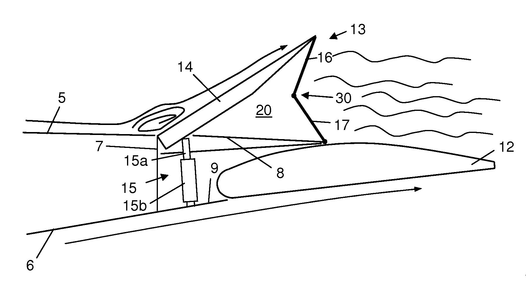
[0037]FIGS. 4-7 show a wing / spoiler assembly. The assembly comprises a wing with an upper cover 5 and a lower cover 6 attached to a rear spar 7. A flap 12 is also pivotally mounted to the rear spar 7 and shown in its retracted (raised) position in FIGS. 4-7. Upper and lower trailing edge panels 8, 9 are mounted to the rear spar and extend to its rear. The trailing edge panels 8, 9 are also supported by trailing edge ribs (not shown) which are attached to and extended aft of the rear spar. A number of spoiler assemblies 13 are pivotally mounted to the trailing edge of the wing. Each spoiler assembly 13 comprises: a spoiler panel 14; a hydraulic actuator 15; and a pair of flow restriction panels 16, 17 which together form a retractable device for restricting circulation of air around a trailing edge of the spoiler panel. The actuator 15 comprises a piston 15a extending from a cylinder 15b. The piston 15a is pivotally connected to the spoiler panel 14 and the cylinder 15b is pivotally...


PUM


Abstract

An aircraft wing load alleviation system incorporating a wing, a spoiler panel (14), a device (16, 17) which restricts circulation of air around a trailing edge of the spoiler and a control system. The spoiler panel is pivotally attached to the wing so that the spoiler panel can be rotated up from a lowered position to a raised position, thereby opening a void between the spoiler panel and the wing. The retractable device can be deployed from a retracted position to an extended position in which it restricts circulation of air around the trailing edge of the spoiler panel and into the void, thus reducing induced drag. The control system is configured to detect or predict an increase in the lift of the wing and rotate the spoiler panel to its raised position in response to a detected or predicted increase in the lift of the wing.

Description

FIELD OF THE INVENTION[0001]The present invention relates to an aircraft wing load alleviation system, and an associated method.BACKGROUND OF THE INVENTION[0002]A spoiler is typically a panel hinged to the upper surface of a wing. Conventionally an array of such spoilers is provided for failsafe purposes. That is, each spoiler is controlled by an independent actuator so that, if one of the actuators fails, the remaining spoilers can still be deployed. The individual spoilers are closely spaced with ideally no gap between the spoilers. Generally, each spoiler is made from solid material such as metal or composite. Between the spoilers in a span-wise sense, solid rubber seals are used to prevent the leakage of airflow while the spoilers are retracted.[0003]The primary function of the spoiler is to reduce lift of the wing, although a secondary effect of the spoiler is to slightly increase the drag of the wing. The drag increase is partially caused by the increase of frontal area due to...

Claims


Application Information

Patent Timeline
IPC IPC(8): B64C3/50B64C13/16B64C9/34
CPCB64C9/10B64C9/323Y02T50/32B64C13/16B64C9/34Y02T50/30
Inventor MATSUDA, YUKITAKA
Owner AIRBUS OPERATIONS LTD
Why Eureka
Try Eureka