Composite l-shaped fitting and method and mould for the production thereof

Active Publication Date: 2011-11-10
SKF AEROSPACE FRANCE SAS
View PDF26 Cites 11 Cited by
  • Summary
  • Abstract
  • Description
  • Claims
  • Application Information

AI Technical Summary

Benefits of technology

[0009]The present invention is aimed at providing an L-shaped fitting obtained after molding of a composite material the new design of which permits not only to meet the above-mentioned specifications, but also to cope with the drawbacks of deterioration when it is stressed in traction or compression, and without exhibiting the drawbacks related to the addition of material.
[0014]This feature namely permits to increase the compression strength, in particular, but not restrictively, when the direction of the compression force is substantially constant and perpendicular to the flat coupling face.

Problems solved by technology

These fittings 1 are subjected to tensile and compression forces, and they must therefore meet strict specifications; however, because they are made out of composite material, these fittings are subjected, during their stress, to bending deformations, which generate a delamination of the fibers.
The solution consisting in making the walls thicker permits to increase only slightly the strength of the structure, while exhibiting other drawbacks such as an increase in size and weight of the fitting.

Method used


Image

  • Composite l-shaped fitting and method and mould for the production thereof
  • Composite l-shaped fitting and method and mould for the production thereof
  • Composite l-shaped fitting and method and mould for the production thereof

Examples


Embodiment Construction

ng,

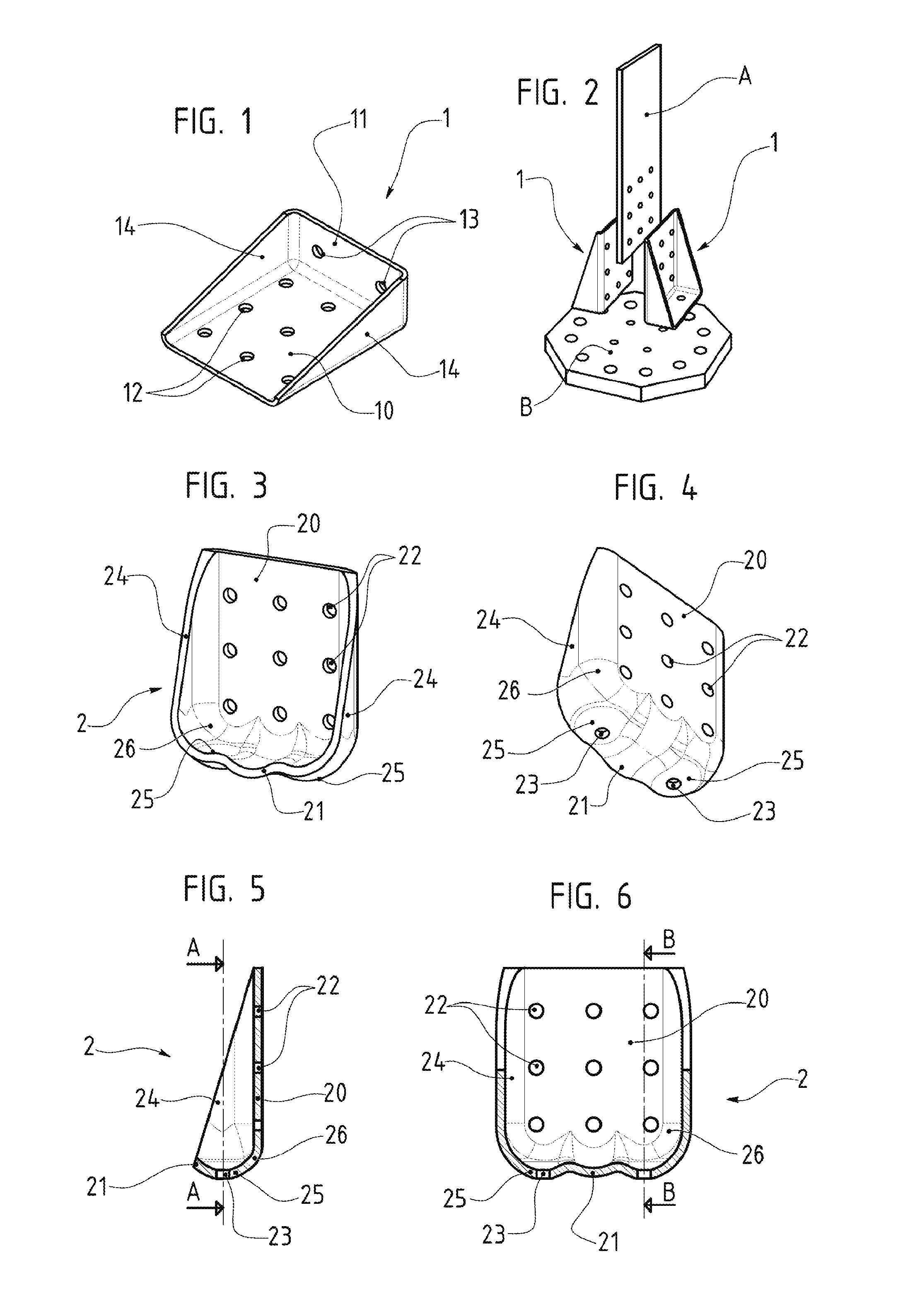
[0030]FIG. 5 represents a schematic and cross-sectional view according to the axis BB of FIG. 6 of the same fitting,

[0031]FIG. 6 represents a schematic and cross-sectional view according to the axis AA of FIG. 5 of the same fitting,

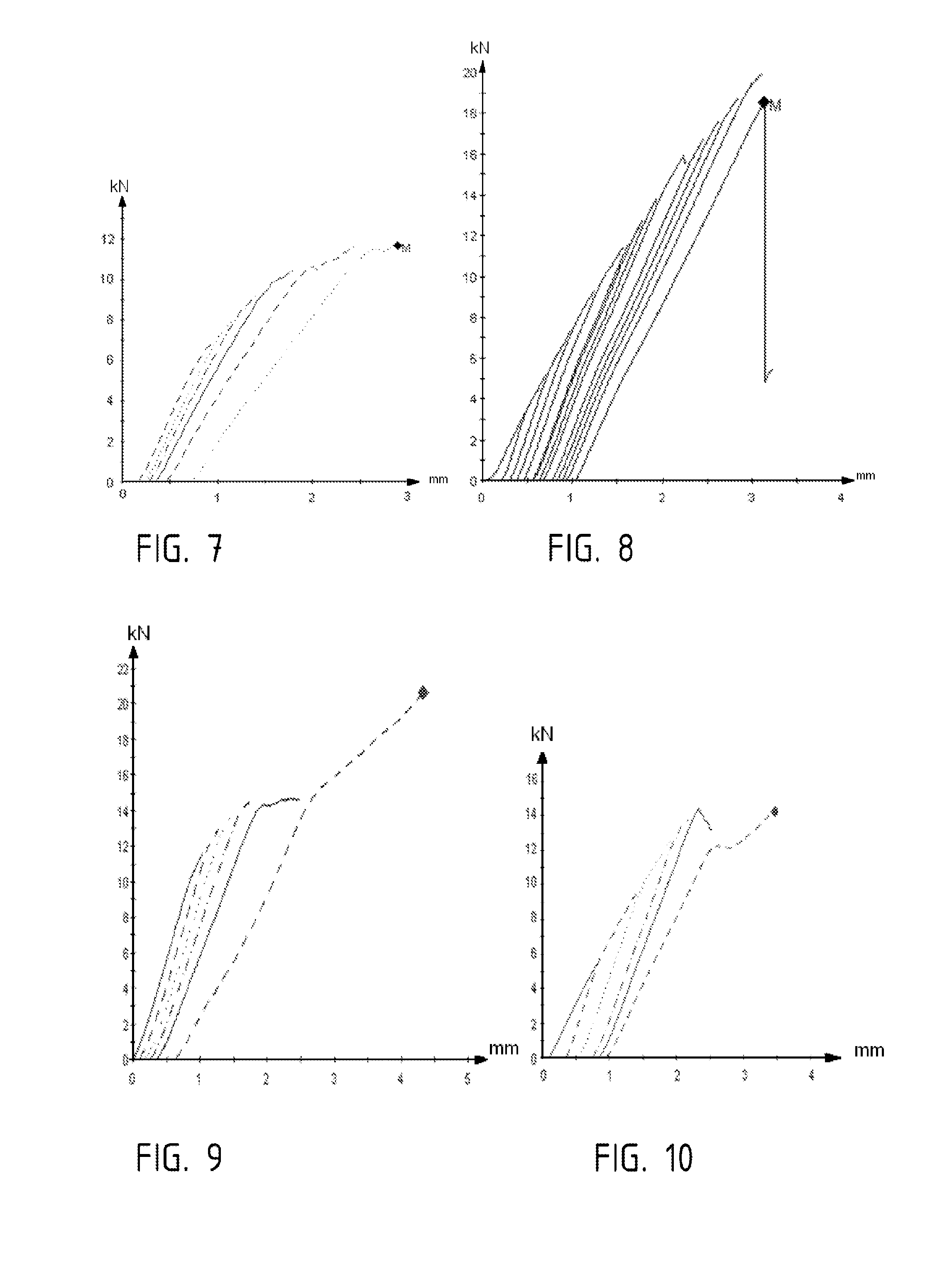
[0032]FIGS. 7 and 8 represent results of tensile tests on fittings,

[0033]FIGS. 9 and 10 represent results of compression tests on fittings,

[0034]FIG. 11 represents a schematic and perspective view of a variant of the L-shaped fitting according to the invention,

[0035]FIG. 12 represents the results of compression tests on the fitting shown in FIG. 11.

[0036]FIGS. 13 and 14 represent schematic plan views of a mold for producing an L-shaped fitting according to the invention.

DETAILED DESCRIPTION OF THE PREFERRED EMBODIMENTS

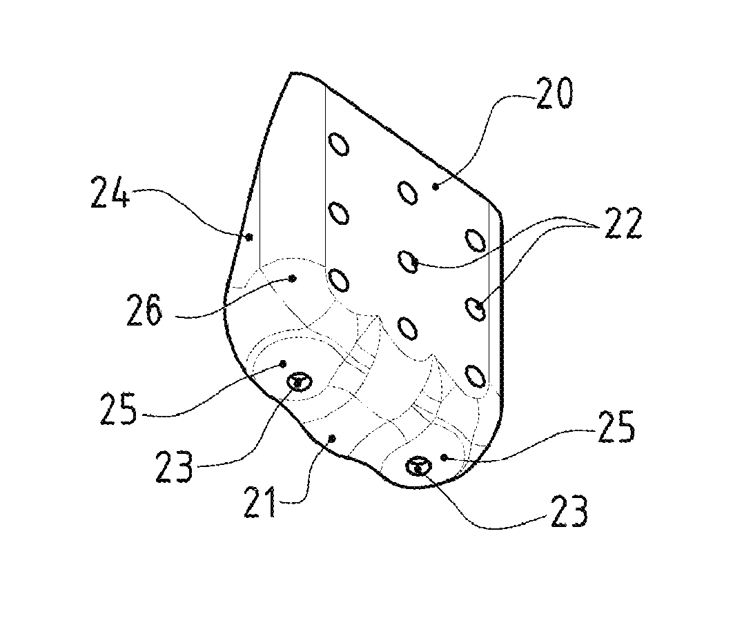
[0037]In FIGS. 3. 4. 5 and 6, one can see an L-shaped fitting 2 according to the invention. This fitting 2 comprises two portions 20 and 21 forming between them an angle, in this case a right angle, having holes 22 and 23, respectively, f...


PUM

PropertyMeasurementUnit
Fractionaaaaaaaaaa
Temperatureaaaaaaaaaa
Pressureaaaaaaaaaa

Abstract

The invention relates to an L-shaped fitting obtained after molding a composite material, including two portions defining an angle therebetween and having holes formed therein for connecting the two portions using an attachment device, and having side reinforcements in the form of brackets. At least one portion has a concave curved profile on the inner side of the fitting, and the hole(s), formed in the portion having a concave curved profile on the inner side are each formed along an axis radial to the curvature.

Description

BACKGROUND OF THE INVENTION[0001](1) Field of the Invention[0002]The object of the present invention is an L-shaped fitting obtained after molding a composite material, as well as the method for the production thereof and the mold for implementing said method.[0003](2) Description of the Prior Art[0004]FIG. 1 of the attached drawing represents an L-shaped fitting 1 made out of composite material presently used, namely in the field of aeronautics, for assembling parts. This fitting 1 is obtained after molding a composite material, it essentially includes two portions 10 and 11 forming between them an angle, in this case a right angle, having holes 12 and 13, respectively, formed therein in order to allow making them integral, and at right angles by means of side reinforcements 14.[0005]Such a fitting 1 is aimed, as shown in FIG. 2, at being used pairwise for assembling and fixing two parts A and B, one of which is perpendicular to the other one, one of both parts, A, being enclosed b...

Claims


Application Information

Patent Timeline
IPC IPC(8): F16M11/00B28B7/28B29C70/34
CPCB29C33/485B29C70/345Y02T50/43B64C2001/0072Y02T50/433B29L2031/3082B29C70/461Y02T50/40
Inventor VALEMBOIS, GUY
Owner SKF AEROSPACE FRANCE SAS
Why Eureka
Try Eureka