Anchor pile apparatus

Inactive Publication Date: 2005-05-12
WHITSETT MICHAEL
View PDF13 Cites 12 Cited by
  • Summary
  • Abstract
  • Description
  • Claims
  • Application Information

AI Technical Summary

Benefits of technology

[0007] It is, therefore, an object of the present invention to provide a novel anchor piling apparatus that is capable of enhancing the total overall load capacity of the piling below the ground line.
[0009] Once the pile sections reach a pre-determined depth, the connection between the drive member and the anchor is severed, allowing withdrawal of the drive member and its subsequent re-use. The pile sections may be selected to have increasingly greater cross sectional area starting from the lowermost pile section to the uppermost pile section. Once the drive member is withdrawn, the pile sections are filled with self-hardening filler material, which will assume the shape of the internal cross section of the pile sections, thereby increasing structural strength of the piling system.

Problems solved by technology

There also exist conditions where the large anchor pile installation is not feasible.
In such cases, the conventional piling systems are not versatile enough to ensure the sufficient tension and compression force required of the piling system.

Method used


Image

  • Anchor pile apparatus
  • Anchor pile apparatus
  • Anchor pile apparatus

Examples


Embodiment Construction

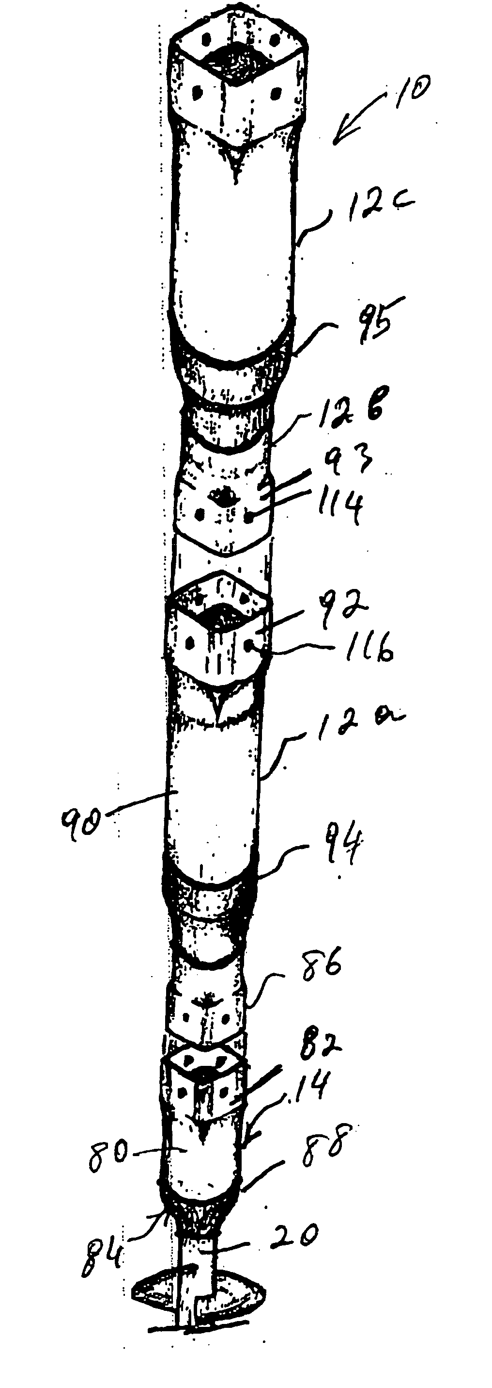
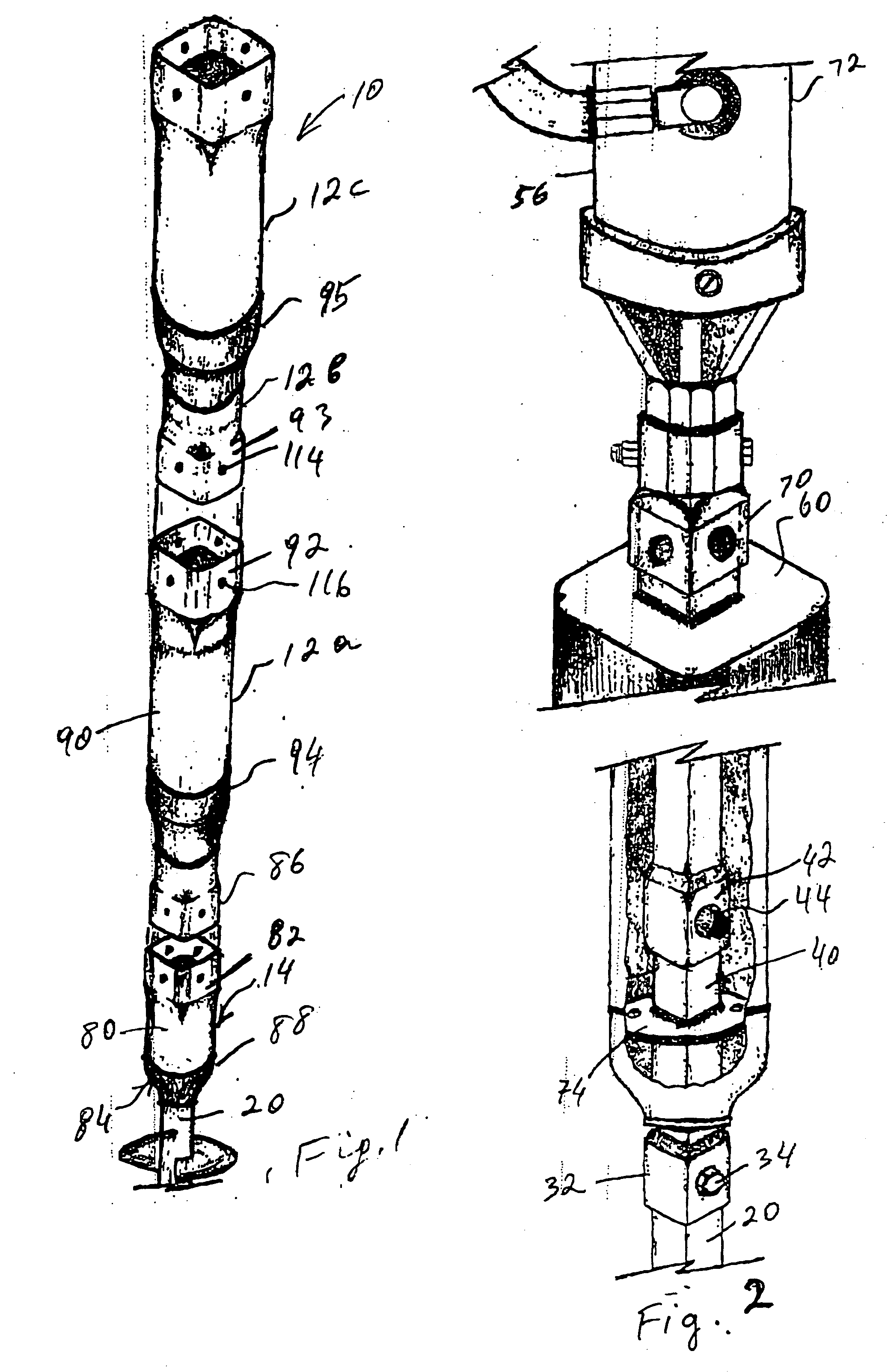
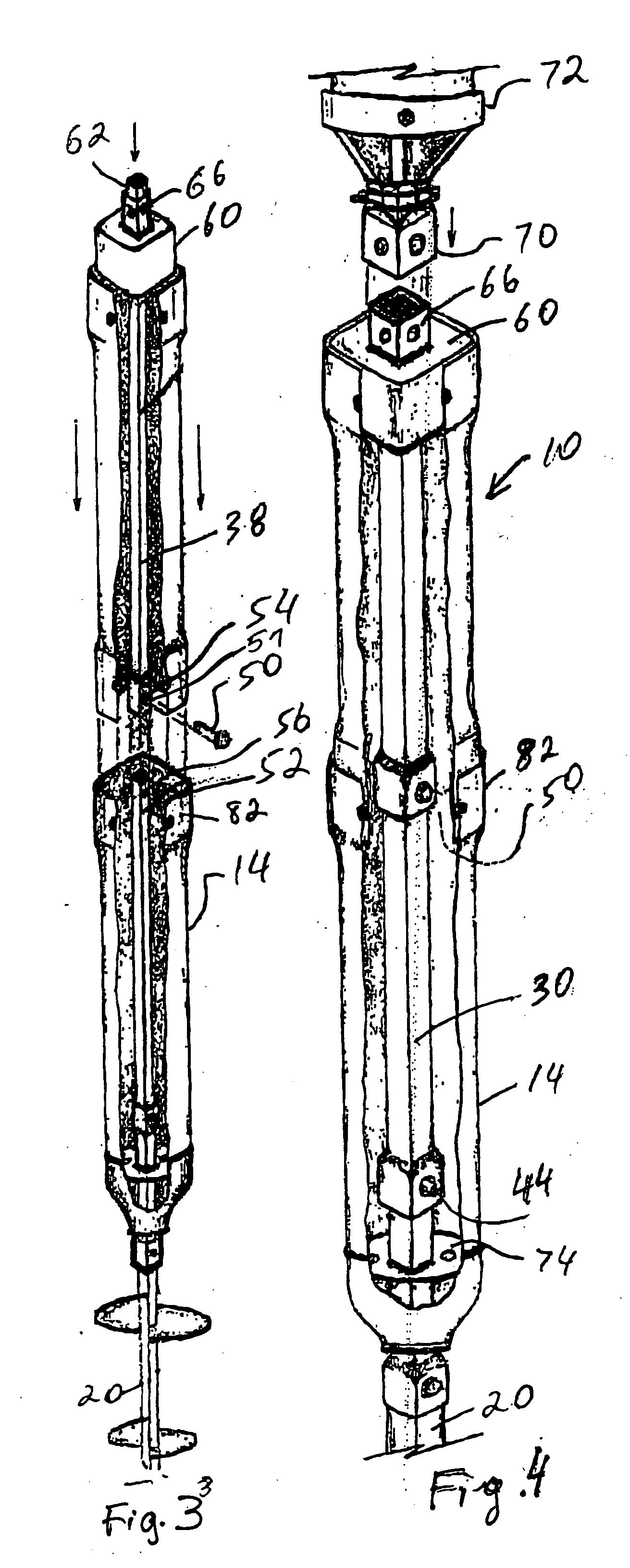
[0032] Turning now to the drawings in more detail, numeral 10 designates the anchor pile apparatus in accordance with the present invention. The anchor piling apparatus 10 comprises a plurality of hollow pile sections 12 connectable end to end in a substantially coaxial alignment. A hollow transition section 14 forms the lowermost of the pile sections 12. One or ore pile sections 12 may be connected above the transition section 14, depending on the depth of insertion of the pile 10 into the soil.

[0033] Secured to a lower end 16 and the transition section 14 is a helical anchor 18, which is adapted to be driven into the soil, followed by the transition section 14 and one or more pile sections 12. The anchor 18 comprises an anchor shaft 20, which carries a plurality of helical disks 22. The anchor shaft 20 is operationally connected with a drive member 30 extending inside the pile sections 12. As can be seen in FIG. 2, a lower connector member 32 interconnects the lowermost portion o...


PUM


Abstract

An anchor pile apparatus has a helical anchor rotatable by a power source through an intermediate drive member. The drive member extends through a plurality of hollow pile sections, which are driven, one by one, into the soil following the penetration of the anchor. In one of the embodiments, the anchor and the pile sections are rotated separately by independent motors, thus expediting the installation of the pile in the pre-determined location.

Description

CROSS-REFERENCE TO RELATED APPLICATIONS [0001] This application is a continuation-in-part application of my co-pending application Ser. No. 09 / 993,321 filed on Nov. 14, 2001 entitled “Piling Apparatus and Method of Installation,” which is a nonprovisional application based on provisional application No. 60 / 248,349 filed on Nov. 14, 2000, the full disclosures of which are incorporated by reference herein and priority of which is hereby claimed.BACKGROUND OF THE INVENTION [0002] The present invention relates to an anchor pile apparatus and, more particularly, to an anchor piling apparatus which includes a helical anchor and one or more hollow pile sections adapted for driving into the soil with a surface mounted power source. [0003] The construction and building industries have long used anchor pile devices for providing structural support to buildings in adverse soil conditions. From the beginning, cylindrical disks were used as part of the anchor devices for penetrating the soil and...

Claims


Application Information

Patent Timeline
IPC IPC(8): E02D5/38E02D5/52E02D5/54E02D5/72
CPCE02D5/38E02D5/72E02D5/54E02D5/52
Inventor WHITSETT, MICHAEL
Owner WHITSETT MICHAEL
Why Eureka
Try Eureka