Multi-piece crankshaft construction

Inactive Publication Date: 2003-02-06
PANTHER MACHINE
View PDF38 Cites 4 Cited by
  • Summary
  • Abstract
  • Description
  • Claims
  • Application Information

AI Technical Summary

Benefits of technology

[0018] The position of the mold recesses for both the main shaft as well as the crankpin, together with the shape of the first mold cavity corresponding to the desired counterweight as well as the second mold cavity corresponding to the desired shape of the flywheel support taper, are machined in the mold with high accuracy. As such, when the crankpin and main shaft are positioned within the mold in the above-described fashion, not only can precise parallelism and radial spacing between the crankpin and main shaft be maintained, but also the precise position of the flywheel support taper as well as the precise position of the flywheel support taper key slot is maintained with a high degree of precision.
[0021] Since the position of the main shaft and crankpin are maintained by the mold at a precise position relative to each other, following the casting operation, precise parallelism between the crankpin and main shaft is established as well as precise position of the flywheel support taper for the crankshaft assembly. Furthermore, the cast material also encases the plate which increases the overall structural strength of the counterweight from that obtained by the thermosetting material alone.

Problems solved by technology

Machining such crankshafts, however, requires specialized equipment and is relatively expensive in manufacturing cost.
A primary disadvantage of these previously known multi-piece crankshafts is that the main shaft and crankpin must be parallel to each other within very high tolerances.
However, during the pressing operation of the main shaft and crankpin into the counterweight, the main shaft and crankpins often become skewed relative to each other and the resulting crankpin assembly must be either corrected by bending the crankpin and main shaft relative to each other or, in some cases, discarded as scrap.
Furthermore, in many cases the precise position of the flywheel support taper together with its key slot may not meet manufacturing tolerances where, during the pressing operation of the main shaft into the counterweight, axial movement of the counterweight relative to the main shaft occurs from spring back or the like.

Method used


Image

  • Multi-piece crankshaft construction
  • Multi-piece crankshaft construction
  • Multi-piece crankshaft construction

Examples


Embodiment Construction

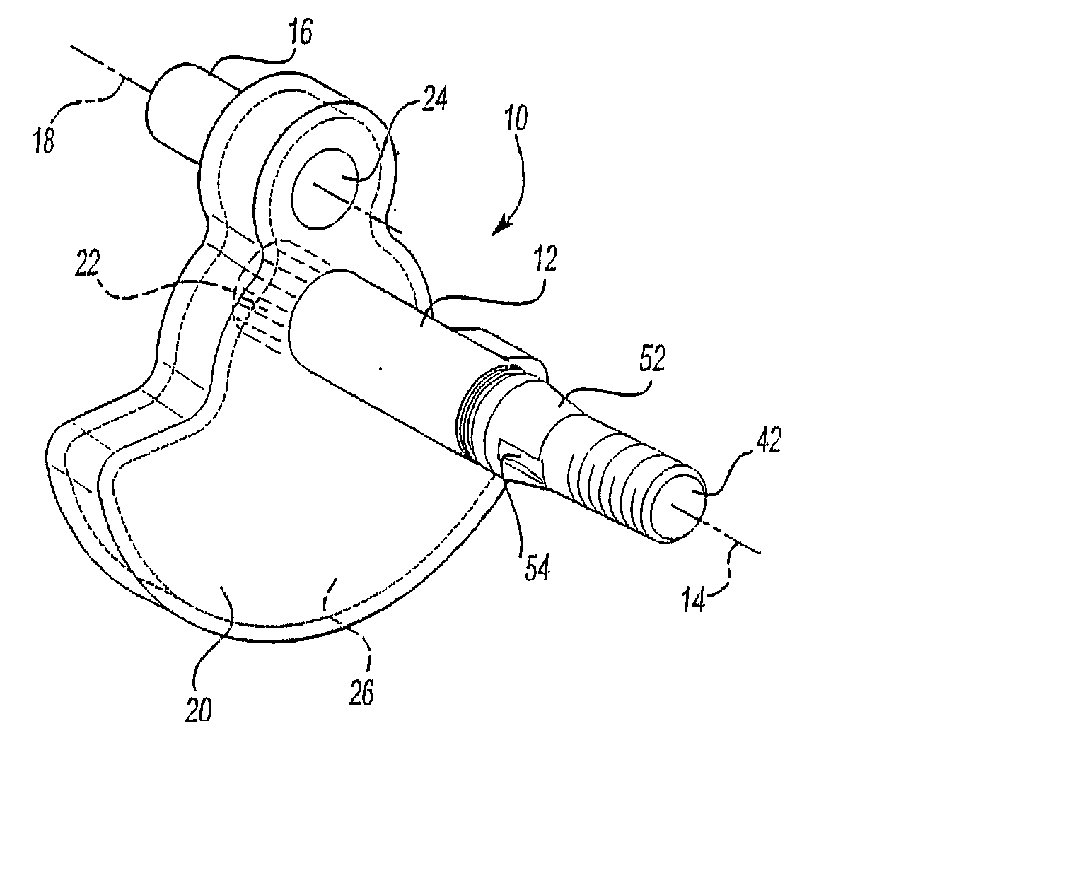
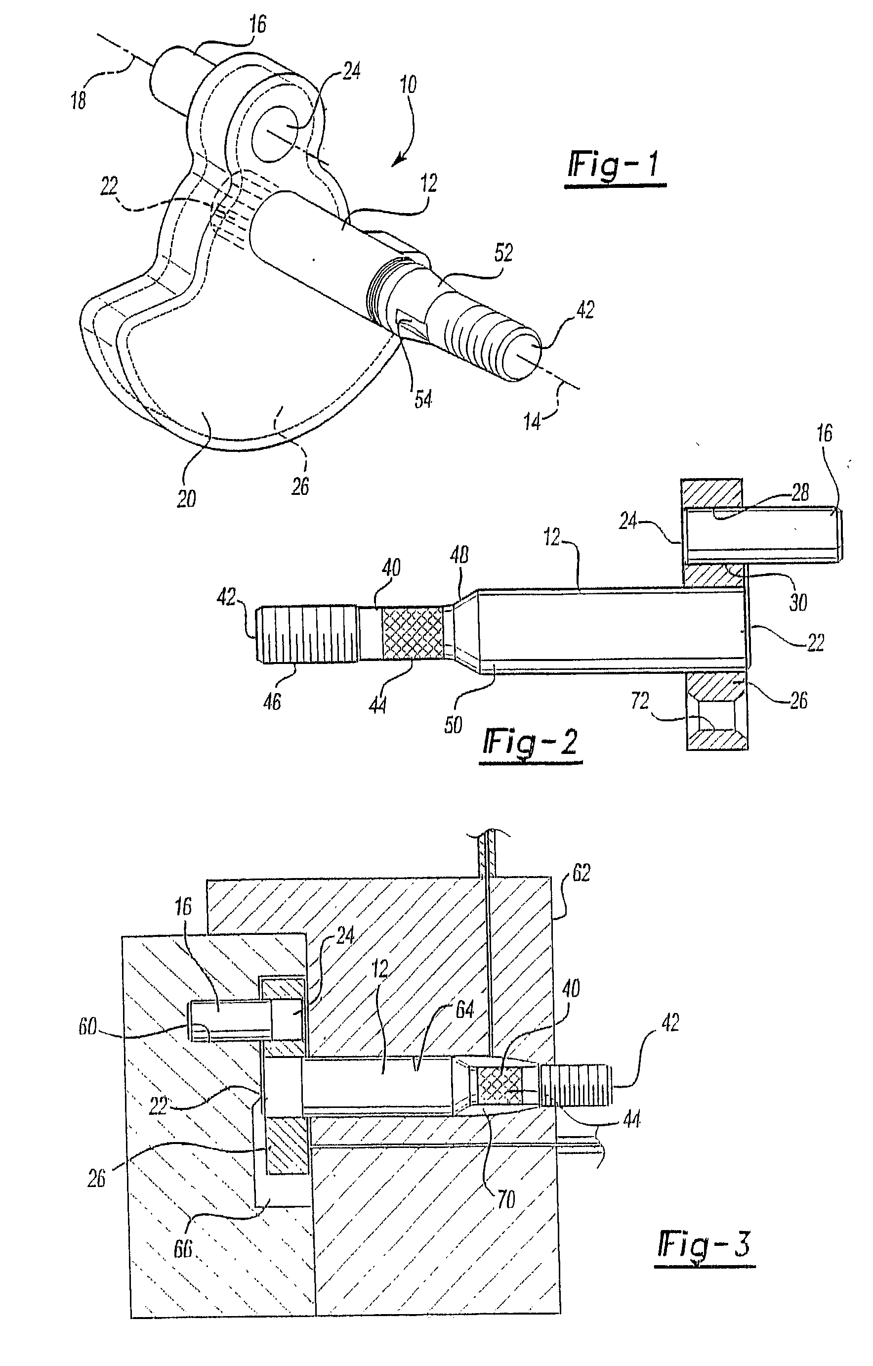
[0029] With reference first to FIG. 1, a preferred embodiment of a crankshaft 10 of the present invention is there shown and comprises an elongated main shaft 12 adapted to rotate about its longitudinal axis 14. The crankshaft 10 also includes a crankpin 16 having a longitudinal axis 18 parallel to but radially spaced from the axis 14 of the main shaft 12.

[0030] A counterweight 20 extends between a first end 22 of the main shaft and a first end 24 of the crankpin 16. The counterweight 20 effectively secures the crankpin 16 and main shaft 12 together.

[0031] In order to strengthen the counterweight 20, a reinforcing plate 26 is contained within the interior of the counterweight 20. The reinforcing plate 26 is constructed of a high strength material, such as steel.

[0032] With reference now to FIG. 2, the reinforcing plate 26 includes a first throughbore 28 and a second throughbore 30. The first throughbore 28 is aligned with the crankpin 16 and adapted to receive the end 24 of the cran...


PUM

PropertyMeasurementUnit
Sizeaaaaaaaaaa
Shapeaaaaaaaaaa

Abstract

A multi-piece crankshaft is disclosed having a shaft with two ends and in which the shaft is adapted to rotate about its shaft axis. A crankpin also has two ends and an axis parallel to but spaced radially outwardly from the shaft axis. The crankpin optionally has at least one indentation. A plate has two spaced openings such that one end of the shaft is positioned in one of the plate openings while one end of the crankpin is placed in the other plate opening. The shaft also includes at least one indentation at a position adjacent its other end. The shaft and crankpin are placed within a mold so that the plate is positioned within a first mold cavity corresponding in shape to the desired counterweight. Simultaneously, the indentation adjacent the other end of the shaft is positioned within a second mold cavity corresponding in shape to a flywheel taper support for the crankshaft. The counterweight and flywheel taper support are then both formed by simultaneously casting a liquid material, such as zinc, into both the first and second mold cavities. Upon cooling, the molten material solidifies thus simultaneously forming the counterweight and flywheel support taper.

Description

[0001] This is a continuation-in-part of U.S. patent application Ser. No. 09 / 859,984 filed May 17, 2001, which is a continuation-in-part of U.S. patent application Ser. No. 09 / 533,917, filed Mar. 23, 2000, which is a divisional of U.S. patent application Ser. No. 09 / 065,155 filed Apr. 23, 1998.[0002] I. Field of the Invention[0003] The present invention relates generally to crankshafts and, more particularly, to a multi-piece crankshaft and method for constructing the same.[0004] II. Description of Related Art[0005] Many previously known crankshafts are made from a heavy single body of cast metal which is then machined so that the main shaft, crankpins and counterweight are all of a one-piece construction. Machining such crankshafts, however, requires specialized equipment and is relatively expensive in manufacturing cost.[0006] There are, however, previously known crankshafts which are constructed from multiple pieces for low cost construction. Such crankshafts are oftentimes used ...

Claims


Application Information

Patent Timeline
IPC IPC(8): F16C3/10
CPCF16C3/10Y10T74/2173Y10T74/2177Y10T74/2175Y10T29/49286Y10T403/4634Y10T74/2183
Inventor LEITH, DONALD G.
Owner PANTHER MACHINE
Why Eureka
Try Eureka