Gas cluster ion beam system with cleaning apparatus

US20110272593A1Active Publication Date: 2011-11-10TEL EPION

Image

  • Gas cluster ion beam system with cleaning apparatus
  • Gas cluster ion beam system with cleaning apparatus
  • Gas cluster ion beam system with cleaning apparatus

Examples


Embodiment Construction

[0032]In the following description, in order to facilitate a thorough understanding of the invention and for purposes of explanation and not limitation, specific details are set forth, such as a particular geometry of the metrology system and descriptions of various components and processes. However, it should be understood that the invention may be practiced in other embodiments that depart from these specific details.

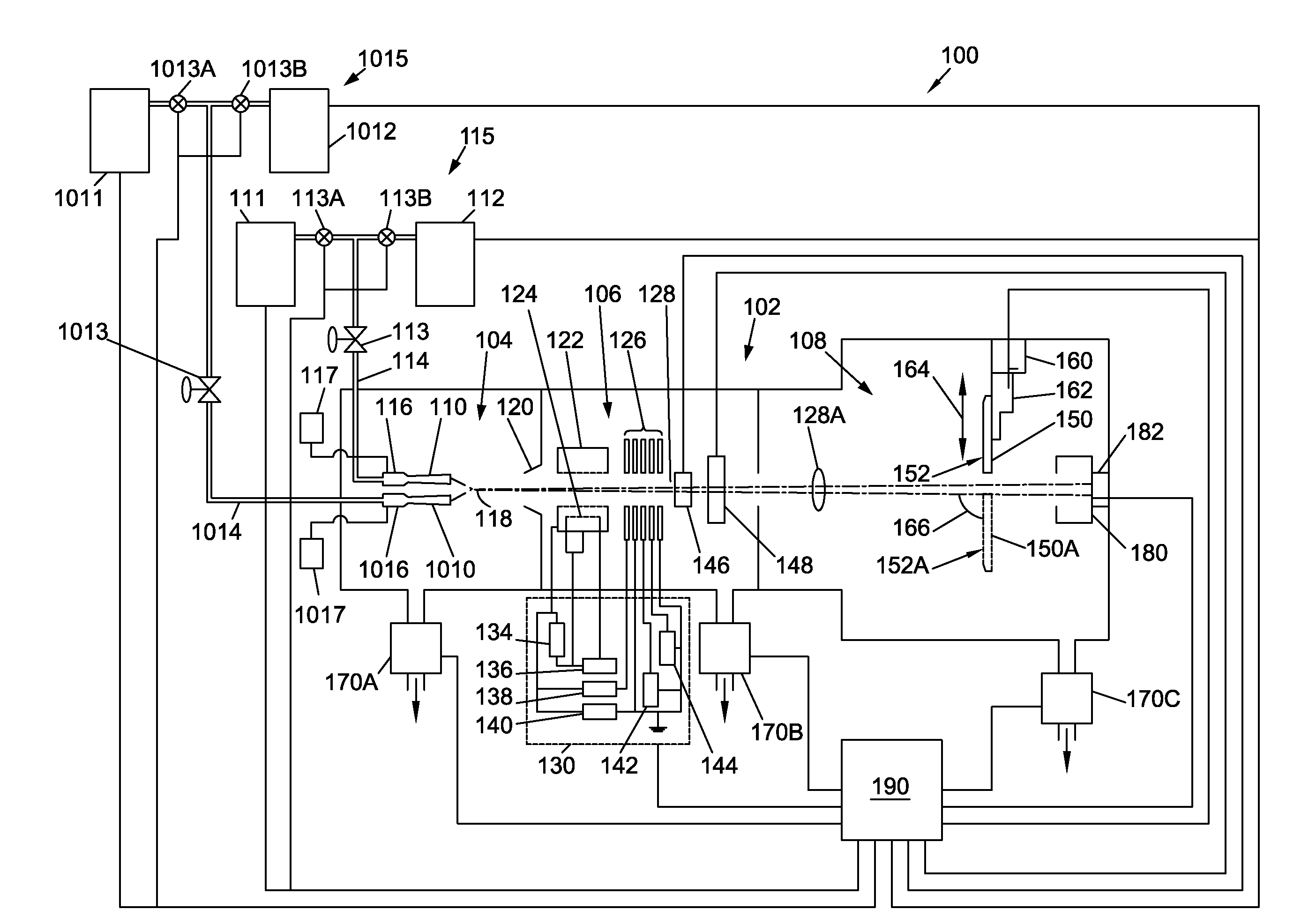
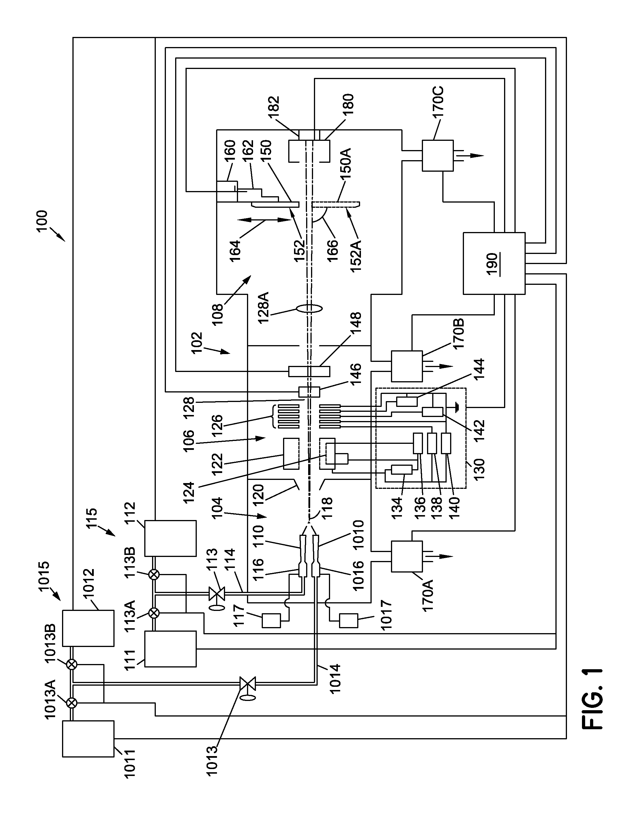
[0033]Referring now to FIG. 1, a GCIB processing system 100 for modifying, depositing, growing, or doping a layer is depicted according to an embodiment. The GCIB processing system 100 comprises a vacuum vessel 102, substrate holder 150, upon which a substrate 152 to be processed is affixed, and vacuum pumping systems 170A, 170B, and 170C. Substrate 152 can be a semiconductor substrate, a wafer, a flat panel display (FPD), a liquid crystal display (LCD), or any other workpiece. GCIB processing system 100 is configured to produce a GCIB for treating substrate 152.

[0034...


PUM


Abstract

A processing system is provided for irradiating a substrate with a gas cluster ion beam (GCIB). The system includes a vacuum vessel that has an interior and is configured to support the substrate therein, and at least one nozzle for forming and emitting a gas cluster beam. The at least one nozzle is configured to direct the gas cluster beam within the vacuum vessel toward the substrate. An ionizer is positioned to ionize the gas cluster beam to form the GCIB. A main gas supply of the system is in fluid communication with the at least one nozzle for supplying gas to the nozzle. The system also includes a plasma-generating apparatus that communicates with the interior of the vacuum vessel and which is configured to receive a cleaning gas and selectively emit plasma for cleaning the interior of the vacuum vessel.

Description

CROSS-REFERENCE TO RELATED APPLICATIONS[0001]This application is related to co-pending U.S. Nonprovisional patent application Ser. No. 12 / 428,945, entitled “MULTIPLE NOZZLE GAS CLUSTER ION BEAM SYSTEM” (Ref. No. EP-166), filed Apr. 23, 2009, which is based on and claims the benefit of and priority to U.S. Provisional Patent Application No. 61 / 149,930, entitled “MULTIPLE NOZZLE GAS CLUSTER ION BEAM SYSTEM AND A METHOD OF OPERATION” (Ref. No. EP-166 PROV), filed on Feb. 4, 2009. This application is also related to co-pending U.S. Nonprovisional patent application Ser. No. 12 / ______, entitled “GAS CLUSTER ION BEAM SYSTEM WITH RAPID GAS SWITCHING APPARATUS,” (Ref. No. EP-173) filed on even date herewith. The entire contents of all of these applications are hereby expressly incorporated by reference herein in their entirety.BACKGROUND OF THE INVENTION[0002]1. Field of the Invention[0003]The invention relates to a system and related methods for irradiating substrates using a gas cluster i...

Claims


Application Information

Patent Timeline
10 Nov 2011
Publication
US20110272593A1
IPC
H01J37/30; H01J37/02
CPC
H01J37/3002; H01J2237/022; H01J2237/0812; H01J2237/3151; H01J2237/0827; H01J2237/3142; H01J2237/0825
Inventors
GRAF, MICHAEL; MITROVIC, ANDREJ