
Method For Optimizing A Cutting Process In Road Milling Machines, As Well As Milling Machine For Machining Road Coverings

a technology of road milling machine and cutting process, which is applied in the direction of slitting machine, construction, way, etc., can solve the problems of low flushing performance, low efficiency of machine operator, and high water consumption, so as to reduce the required tank size, reduce the total amount of cooling liquid to be stored, and prevent excessive water use

Inactive Publication Date: 2011-11-10
WIRTGEN GMBH
View PDF5 Cites 6 Cited by
  • Summary
  • Abstract
  • Description
  • Claims
  • Application Information

AI Technical Summary

Benefits of technology

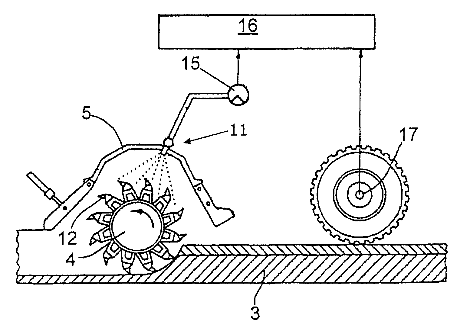
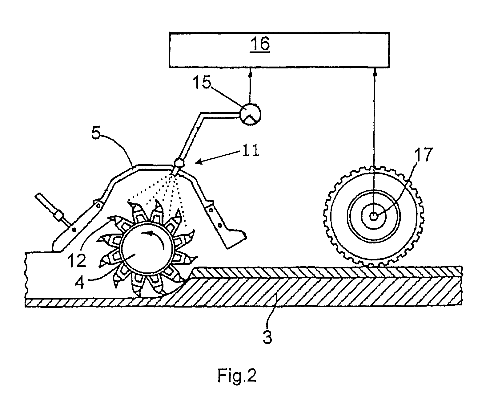
[0013]The invention advantageously provides that at least one parameter representative of the instantaneous power output of the milling device is taken and that the supplied amount of cooling liquid is controlled in dependence on the at least one parameter representative of the instantaneous power output of the milling device. The invention permits an adaptation of the instantaneously supplied amount of cooling liquid to the instantaneous power output of the milling device so that the total amount of cooling liquid to be stored can be considerably reduced, an adaptation to the tool life of the milling device being simultaneously possible in such a manner that the tanks for the cooling liquid do not have to be refilled until other maintenance works on the road milling machine, e.g., a change of tools, become necessary. This not only prevents an excessive use of water but also excludes unnecessary stop periods of the road milling machine. Moreover, a reduction of the required tank size can be achieved by supplying the cooling liquid in accordance with the requirement whereby the total machine weight can be reduced as well. Therefore, it is sufficient to carry an amount of water that suffices for one working shift. In summary, the advantages of the invention are to be seen in the reduction of the water consumption and tool wear as well as in the reduction of the work stops for refilling the water supply or changing a tool.
[0014]A parameter representative of the power output can be formed of the current milling depth and the current advance speed.
[0015]The current measuring or setting values are taken; typically, the milling depth is set and maintained as a constant value and the advance speed may vary from a preset value.
[0016]Alternatively, the at least one parameter representative of the power output can be formed of the current hydraulic pressure of the traveling mechanism at a constant flow rate or of the current hydraulic pressure and the current flow rate of the hydraulic oil of the traveling mechanism.
[0017]According to another alternative, the parameter representative of the power output may consist of the measured torque at a constant speed of the milling device drive.
[0018]According to another alternative, a parameter representative of the power output consists of the current hydraulic pressure in the lifting columns of the chassis of the milling machine. At a lower milling output of the milling device, a higher pressure is built up in the lifting columns as at a higher milling output where the chassis is relieved because of the forces occurring.
[0019]Finally, the at least one parameter representative of the power output may also be detected from the characteristics available in an electronic motor controlling means of the drive motor.
[0020]According to a further development of the invention, it may be provided that the temperature of a milling tool of the milling device or of several milling tools is taken as a parameter representative of the instantaneous power output, compared with a preset nominal temperature value and that the supplied amount of cooling liquid is regulated in dependence on the difference between the nominal temperature value and the measured temperature value. Thus, the cooling capacity of the cooling liquid can be regulated in dependence on the instantaneous power output of the milling device.
[0021]According to another further development of the invention, it may be provided that the control or regulation of the cooling liquid amount is corrected by constant characteristics specific for a machining task and that the supplied amount of cooling liquid is read out from a multidimensional characteristic diagram in dependence on the at least one parameter and the specific characteristics.

Problems solved by technology

A drawback of this solution is a relatively high water consumption resulting from that the machine operator:has to start up the pump already before the actual milling process begins since the machine operator is given a plurality of other controlling and setting tasks in the initial phase until a continuous milling process has been achieved,lets the water flow during short sudden interruptions,the water flows on after the end of the milling process until the pump is switched off,on principle, the flow rate is set too high for reasons of uncertainty,the flow rate is set according to the greatest need on the distance to be milled.
In case of atomizing the cooling liquid, however, the cooling effect is good, on the one hand, but, on the other hand, the flushing performance is bad.
With existing road milling machines, it is only possible to switch the water supply on and off or, if necessary, to adapt it to the different working width of the milling device by switching off some of the spray nozzles.
This has the disadvantage that a metering of the cooling liquid corresponding to the need is not possible and that much space is required for the water tank for the water supply to prevent that work has to be interrupted because a refill with water has become necessary.

Method used


Image

  • Method For Optimizing A Cutting Process In Road Milling Machines, As Well As Milling Machine For Machining Road Coverings
  • Method For Optimizing A Cutting Process In Road Milling Machines, As Well As Milling Machine For Machining Road Coverings
  • Method For Optimizing A Cutting Process In Road Milling Machines, As Well As Milling Machine For Machining Road Coverings

Examples


Embodiment Construction

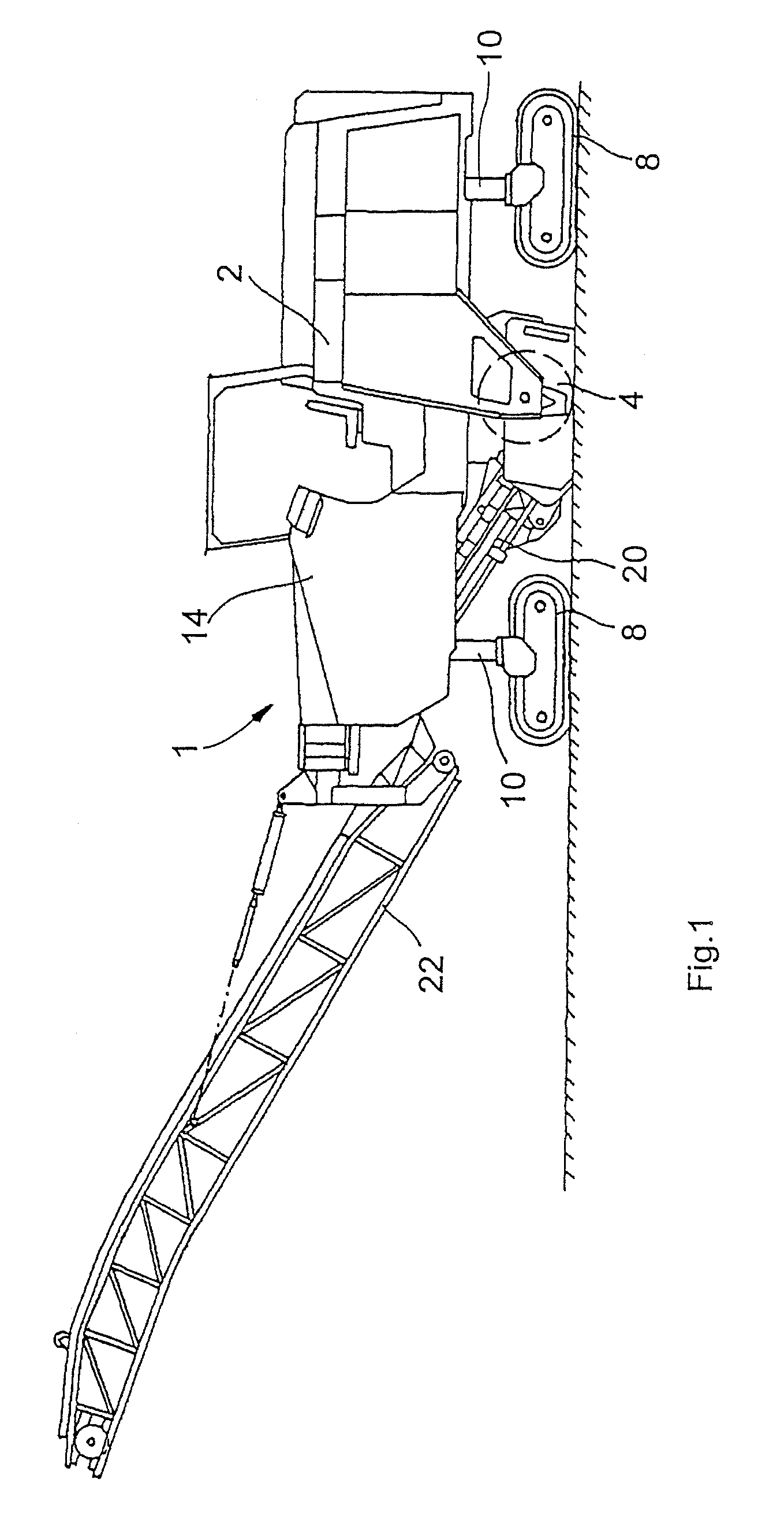
[0032]Road milling machines are employed for the continuous removal of road coverings. These machines are offered with different working widths or can be fitted with milling devices of different widths. The road milling machines are able to work at a milling depth of a few millimeters up to the complete covering thickness of up to 30 centimeters and more. Depending on the application, the milling device can be fitted with a different number and / or a different kind of carbide-tipped parallel shank tools. In case of the so-called precision milling, the road covering is only slightly milled off to obtain a plane pavement with good grip which receives no further treatment. Here, up to 400 tools and more are used per running meter of working width. In contrast thereto, milling devices 4 are used in the so-called complete removal, the milling of the entire road covering in one working cycle, which only have 80 tools and less per running meter of working width. Moreover, the employed milli...


PUM


Abstract

In a method for optimizing a cutting process in milling machines which are used to machine road coverings, which comprise a milling device fitted with milling tools which is sprayed with liquid in order to cool the milling tools, in addition to a drive motor, the following steps are provided: detection of the at least one parameter which is representative of the instantaneous power output of the milling device and controlling the amount of cooling liquid supplied according to the at least one parameter which is representative of the instantaneous power output of the milling device.

Description

BACKGROUND OF THE INVENTION[0001]The invention relates to a method for optimizing a cutting process in road milling machines as well as such a road milling machine.[0002]For increasing the tool life of a milling device fitted with milling tools, it is known with road milling machines to spray the milling tools with water by means of a spraying means, e.g., several spray nozzles arranged next to each other. They are supplied via a tank carried along and a pump. For the duration of the work, the machine operator switches on the pump. In technically further advanced machines, it is already possible today that the machine operator sets the flow rate of the pump. A drawback of this solution is a relatively high water consumption resulting from that the machine operator:[0003]has to start up the pump already before the actual milling process begins since the machine operator is given a plurality of other controlling and setting tasks in the initial phase until a continuous milling process...

Claims


Application Information

Patent Timeline
Patent Type & Authority Applications(United States)
IPC IPC(8): E01C23/12E21C35/24E21C35/00E01C23/088
CPCE01C23/127E01C23/088
Inventor GAERTNER, OLAFSIMONS, DIETER
Owner WIRTGEN GMBH
Learn More