Illumination device, display device, data generation method, data generation program and recording medium

a display device and display device technology, applied in the direction of instruments, computing, electric digital data processing, etc., can solve the problems of insufficient power consumption reduction, unperceived brightness of planar light in the perimeter, and insufficient brightness, so as to reduce the burden on control performed by a control unit, the distribution of brightness is relatively large, and the brightness distribution is relatively large.

Inactive Publication Date: 2011-11-10
SHARP KK
View PDF6 Cites 3 Cited by
  • Summary
  • Abstract
  • Description
  • Claims
  • Application Information

AI Technical Summary

Benefits of technology

[0024]With the illumination device of the present invention, it is possible to change the distribution of brightness of planar light by performing brightness correction processing along at least two directions within a plane of the planar light. Hence, in the brightness correction processing, for example, image data on each of light sources that generate the planar light is not analyzed, and thus a burden imposed on control performed by a control unit is relatively lowered.
[0025]On the other hand, since the planar light undergoes change which cannot be produced by brightness correction processing that is performed along one direction within the plane of the planar light, the distribution of brightness relatively greatly varies. Thus, the illumination device can generate the planar light having the distribution of brightness that is suitable for the reduction of the power consumption.

Problems solved by technology

However, in a human visual characteristic, uneven brightness of the planar light in the perimeter and with a low brightness, in particular, is not perceived.
However, in the backlight unit 169, since the distribution of brightness in a direction q in which the fluorescent tubes 191 extend cannot be changed, the power consumption is not sufficiently reduced.

Method used


Image

  • Illumination device, display device, data generation method, data generation program and recording medium
  • Illumination device, display device, data generation method, data generation program and recording medium
  • Illumination device, display device, data generation method, data generation program and recording medium

Examples


first embodiment

[0047]An embodiment of the present invention will be described below with reference to accompanying drawings. For convenience, member symbols or the like may be omitted; in this case, other drawings should be referenced. For convenience, hatching may be performed even in a diagram other than a cross-sectional view. Values mentioned herein are only an example; the present invention is not limited to these values.

[0048]FIG. 18 is an exploded perspective view showing a liquid crystal display device (display device) 89. As shown in FIG. 18, the liquid crystal display device 89 includes a liquid crystal display panel (display panel) 79, a backlight unit (illumination unit) 69 and a housing HG (HG1 and HG2) that sandwiches them.

[0049]The liquid crystal display panel 79 employs an active matrix system. Hence, in the liquid crystal display panel 79, liquid crystal (not shown) is sandwiched between an active matrix substrate 71 to which active elements such as unillustrated TFTs (thin film t...

second embodiment

[0126]A second embodiment will be described. Members having the same functions as the members used in the first embodiment are identified with common symbols, and their description will not be repeated. In the present embodiment, a description will be given of: a case where the brightness correction processing is not performed; and with what parameter any one of a plurality of filters FT (X, Y) is selected when the brightness correction processing is performed.

[0127]As described in the first embodiment, there are a plurality of filters FT (X, Y) such as the filter FT1 (X, Y) [brightness correction (high) type], the filter FT2 (X, Y) [brightness correction (medium) type] and the filter FT3 (X, Y) [brightness correction (low) type]. However, the brightness correction processing is not necessarily performed by the brightness correction portion 21 (and therefore the microcomputer unit 11). For example, on the liquid crystal display panel 79, the basic video signal that is image data is ...

third embodiment

[0138]A third embodiment will be described. Members having the same functions as the members used in the first and second embodiments are identified with common symbols, and their description will not be repeated. In the present embodiment, a description will be given of which one of a plurality of filters FT (X, Y) is selected with a parameter other than the display mode.

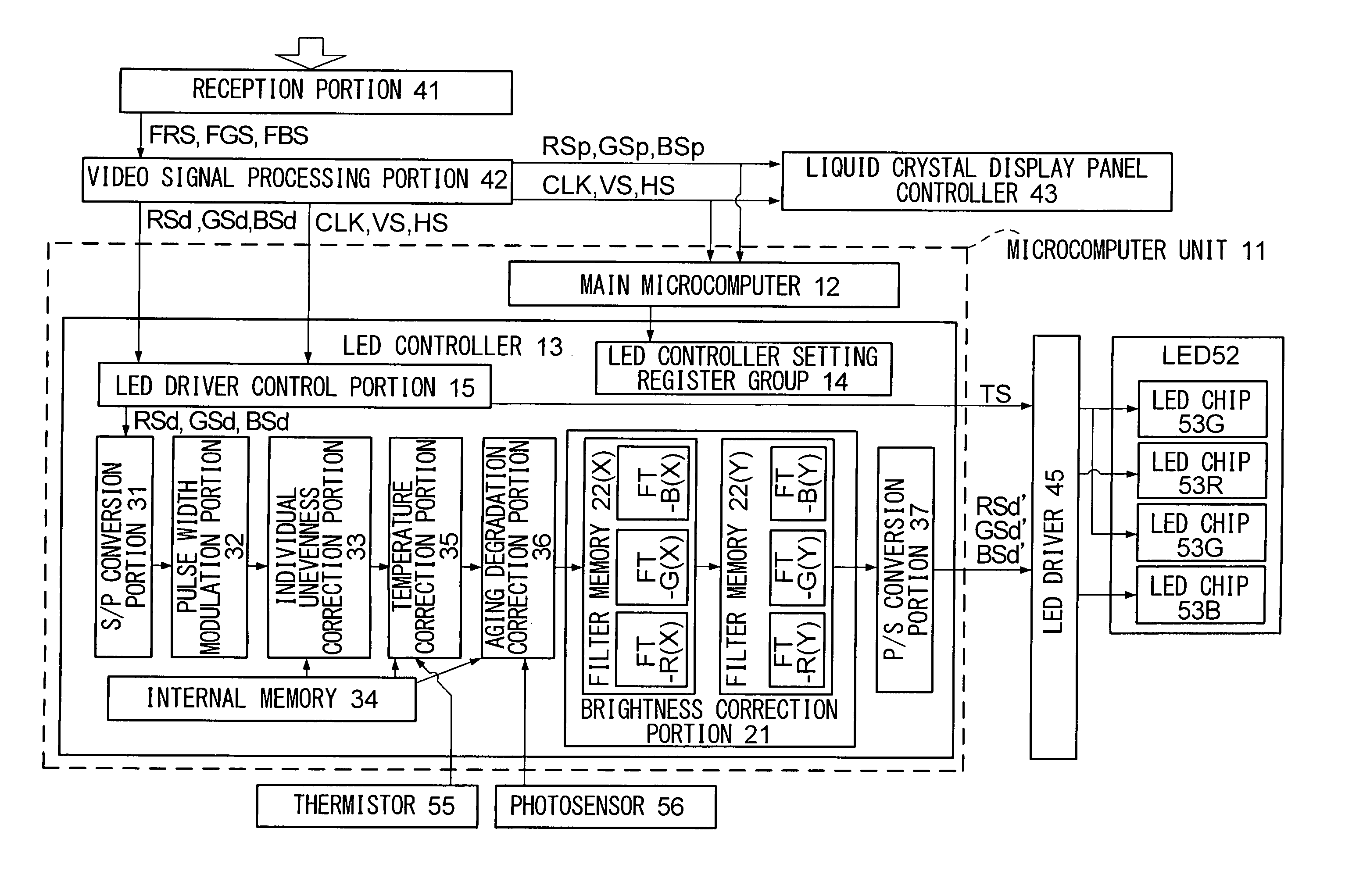
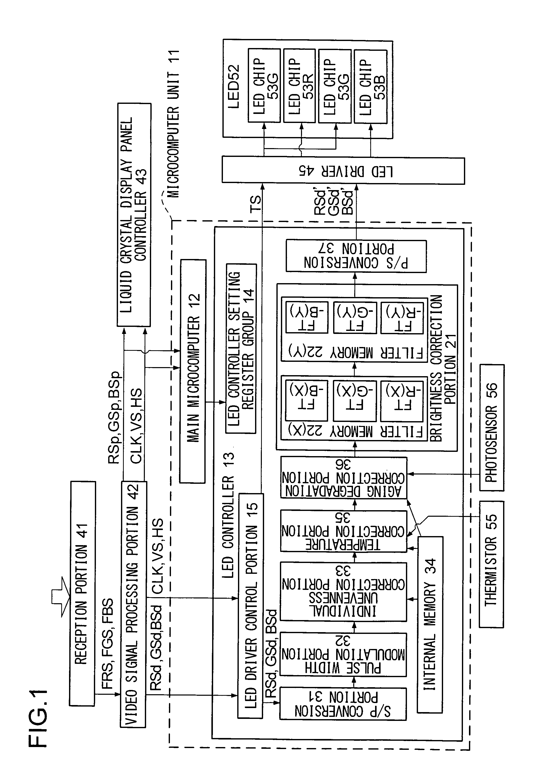
[0139]One of the functions included in the main microcomputer 12 of the microcomputer unit 11 is the function of detecting an average picture level (APL). This APL detection function is to determine the average value (APL value) of gradation of an image displayed on the liquid crystal display panel 79. For example, as shown in FIG. 1, the main microcomputer 12 receives the panel processing color video signals (RSp, GSp and BSp) and the synchronization signals related to these signals, and thereby specifies an image displayed in one frame period and calculates the APL value of gradation of the image.

[0140]For exampl...


PUM


Abstract

Under management by a main microcomputer, an LED controller performs, along at least two directions within a plane of planar light formed by LEDs arranged in a matrix, brightness correction processing for adjusting the distribution of brightness of the planar light on light source color video signals to convert them into light source color video signals.

Description

TECHNICAL FIELD[0001]The present invention relates to an illumination device such as a backlight unit and a display device (such as a liquid crystal display device) incorporating an illumination device. The present invention also relates to a method of generating light amount adjustment data for controlling the light source of an illumination device, a program for generating the light amount adjustment data and a storage medium for storing the data generation program.BACKGROUND ART[0002]In a backlight unit 169 in which fluorescent tubes 191 as shown in FIG. 20 are arranged throughout and which emits planar light, it is easy to change the distribution of brightness in a direction p in which the fluorescent tubes are aligned. For example, in the aligned fluorescent tubes 191, when the brightness of the fluorescent tubes 191 around the ends is set lower than that of the fluorescent tubes 191 around the center, a brightness distribution diagram (brightness distribution diagram specified...

Claims


Application Information

Patent Timeline
Patent Type & Authority Applications(United States)
IPC IPC(8): G09G5/10
CPCG09G3/3413G09G3/342G09G3/3611G09G2330/021G09G2320/041G09G2320/0646G09G2320/0242
Inventor FUJIWARA, KOHJIMURAI, TAKAYUKIICHIOKA, HIDEKI
Owner SHARP KK
Why Eureka
Try Eureka