Swath printer and method for applying an ink image to a receiving medium using a swath printer

US20110273504A1Inactive Publication Date: 2011-11-10OCE TECH

Image

  • Swath printer and method for applying an ink image to a receiving medium using a swath printer
  • Swath printer and method for applying an ink image to a receiving medium using a swath printer
  • Swath printer and method for applying an ink image to a receiving medium using a swath printer

Examples


Embodiment Construction

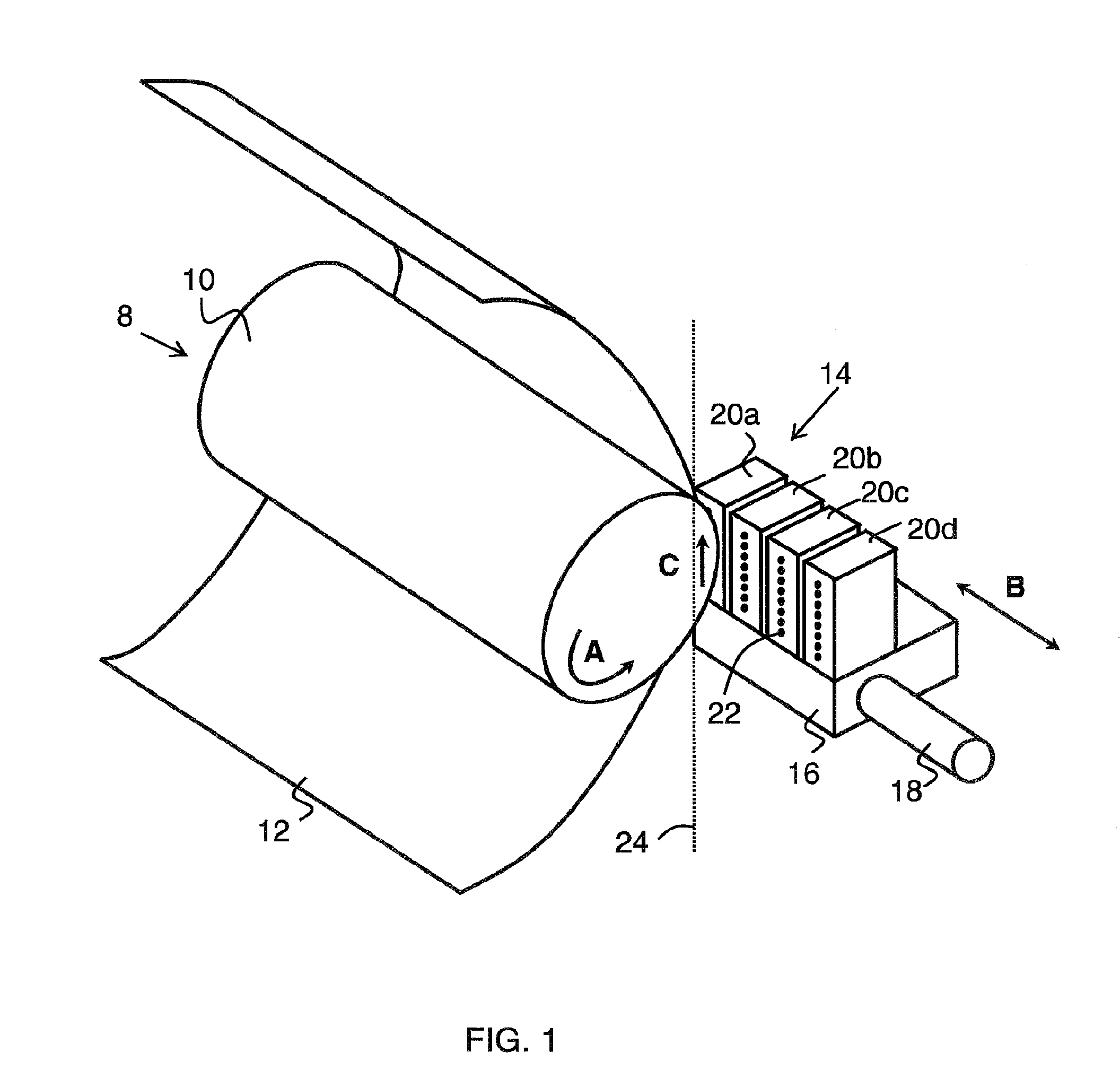
[0033]FIG. 1 schematically depicts a typical setup of a swath type printer, such as an ink jet printer, comprising a multi-nozzle print head 14 that is mounted on a carriage 16. The carriage 16 is guided on guide rails 18, on which the carriage 16 can travel back and forth across a receiving medium 12, such as a sheet of paper, in a direction indicated with a double arrow B. By moving the carriage 16 that carries the print head 14 along the guide rails 18, an image swath (i.e. an image strip with several dot lines) can be printed on the receiving medium 12 with each pass of the print head 14. The direction of movement B is also called the scan direction or scan axis of the printer.

[0034]In the example of FIG. 1, the receiving medium 12 is transported by means of a rotary unit 8 having a feed roller 10. However, it is also possible that the receiving medium 12 is, for example, placed on a substantially flat surface over which it is transported with respect to the print head 14, or ov...


PUM


Abstract

A swath printer includes a print head that is moveable along a scan direction for applying an ink image to a receiving medium. A transport mechanism is configured to move the receiving medium and the print head with respect to each other in a transport direction that is substantially orthogonal to the scan direction. A first sensor is arranged to detect a position of a first reference pattern present on the receiving medium in a first area thereof, and a second sensor is arranged to detect a position of a second reference pattern present on the receiving medium in a second area thereof. A controller is provided to control the printer on the basis of the detected positions of the reference patterns during use of the printer.

Description

CROSS-REFERENCE TO RELATED APPLICATIONS[0001]This application is a Continuation of copending PCT International Application No. PCT / EP2009 / 064579 filed on Nov. 4, 2009, which designated the United States, and on which priority is claimed under 35 U.S.C. §120. This application also claims priority under 35 U.S.C. §119(a) on Application No. 08168823.6, filed in Europe on Nov. 11, 2008, 2008. The entire contents of each of the above documents is hereby incorporated by reference into the present application.BACKGROUND OF THE INVENTION[0002]1. Field of the Invention[0003]The present invention relates to the field of printers. In particular the present invention relates to the field of swath printers, such as inkjet printers. Furthermore, the present invention relates to a method of applying an ink image to a receiving medium using a swath printer.[0004]2. Description of Background Art[0005]Swath-type printers and methods applying an ink image to a receiving medium using a swath printer ar...

Claims


Application Information

Patent Timeline
10 Nov 2011
Publication
US20110273504A1
IPC
B41J29/38
CPC
B41J2/2128; B41J13/0027; B41J11/46; B41J11/008; B41J25/001
Inventors
BOESTEN, HUBERTUS M.J.M.; VAN DE VEN, RICHARD J.M.