Method for correcting the outputs of vehicle behavior sensor

a technology for vehicle behavior and outputs, applied in the field of vehicle behavior sensor output correction, can solve the problems of difficult to arrange such sensors, difficult to position sensors, and method cannot correct the outputs of sensors with the onboard device mounted on the vehicle, etc., to achieve convenient mounting, easy correction, and easy positioning of the substrate

Inactive Publication Date: 2009-11-03
ADVICS CO LTD
View PDF52 Cites 10 Cited by
  • Summary
  • Abstract
  • Description
  • Claims
  • Application Information

AI Technical Summary

Benefits of technology

[0012]Besides the deviations θx and θy, the deviation θz of the first and second sensor elements about the Z-axis in the XY plane (yaw) may be calculated. With this arrangement, the outputs of the sensor elements can be more accurately corrected based on the deviations θx and θy and the deviation θz.
[0013]While the vehicle is traveling in a straight line on a horizontal surface, the acceleration Gy in the Y-axis direction is zero. Thus, from the outputs of the vehicle behavior sensor elements, and from the fact that the true acceleration of the vehicle in the Y-axis direction is zero, or from the acceleration G0 in the travel direction of the vehicle as detected based on signals from onboard wheel speed sensors while the vehicle is traveling in a straight line on a horizontal surface, and the deviations θx and θy, it is possible to calculate the deviations θz of the vehicle behavior sensor elements. Based on the thus calculated deviations θx, θy and θz, it is possible to correct the outputs of the vehicle behavior sensor elements.
[0019]In this state, errors in the outputs of the vehicle behavior sensor elements are detectable. Since such errors are small, they can be easily corrected. It is much easier to position the substrate such that its mounting surface is perpendicular to or parallel to the vertical line than to position the individual sensor elements such that their sensing directions are perpendicular to or parallel to the vertical line.
[0020]According to the present invention, it is possible to correct the outputs of vehicle behavior sensor elements with high accuracy even if the sensor elements are not positioned exactly as intended. Thus, it is possible to accurately detect the behavior of the vehicle from the outputs of the sensor elements.

Problems solved by technology

But practically, no matter how carefully such vehicle behavior sensors are mounted on a vehicle, it is difficult to arrange such sensors such that the sensing direction of each sensor precisely coincides with the intended direction of the vehicle.
Especially if such vehicle behavior sensors are mounted e.g. in a vehicle control device of the above-described type, it is more difficult to position the sensors such that the sensing direction of each sensor precisely coincides with the intended direction of the vehicle than when mounting such sensors directly on the vehicle frame.
Thus, while the method disclosed in the above publication can correct the outputs of the sensors when the sensors are mounted in the onboard device, the method cannot correct the outputs of the sensors with the onboard device mounted on the vehicle.
Also, this publication fails to consider gain errors inherent to respective sensors.
The outputs of conventional vehicle behavior sensors were therefore not sufficiently reliable and more accurate vehicle behavior sensors are desired.

Method used


Image

  • Method for correcting the outputs of vehicle behavior sensor
  • Method for correcting the outputs of vehicle behavior sensor
  • Method for correcting the outputs of vehicle behavior sensor

Examples


Embodiment Construction

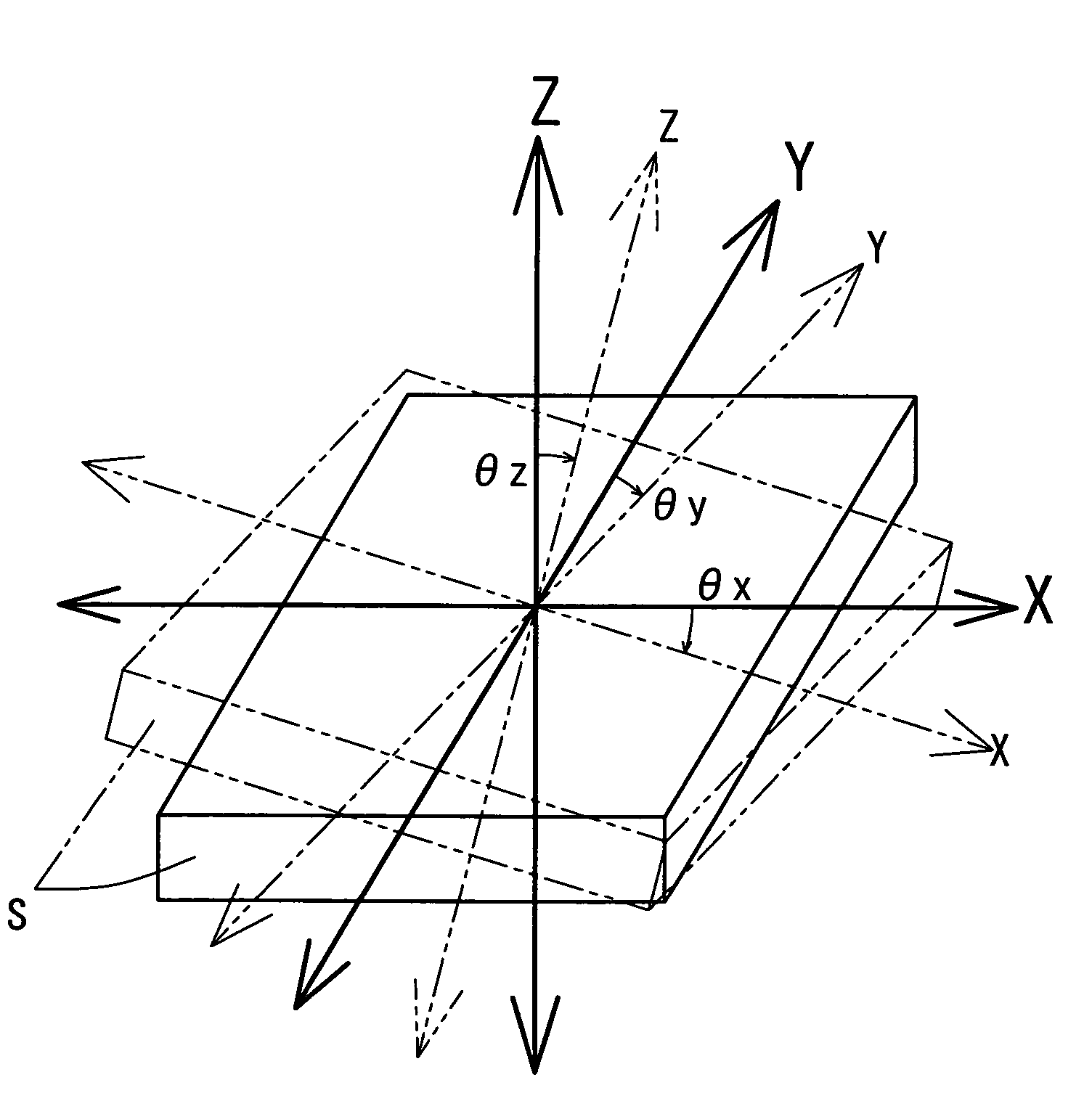
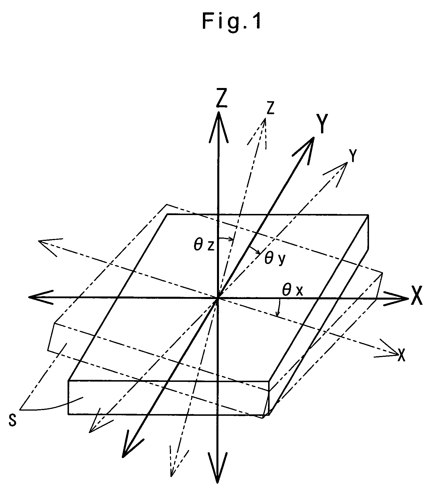
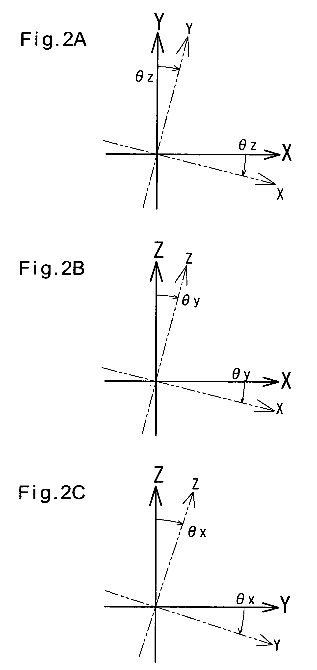
[0035]From one aspect of the invention, there is provided a method for correcting outputs of a vehicle behavior sensor assembly of a vehicle control device including an electronic control unit, the vehicle behavior sensor assembly S comprising a first acceleration sensor element Sx for detecting an acceleration of a vehicle A on which the vehicle control device is mounted in an X-axis direction in which the vehicle travels, and a second acceleration sensor element Sy for detecting an acceleration of the vehicle in a Y-axis direction that is perpendicular to the X-axis direction, the electronic control device being configured to control the behavior of the vehicle based on signals from the first and second acceleration sensor elements, the method comprising mounting the sensor assembly on the vehicle A, keeping the vehicle A in a stationary state with the X-axis and Y-axis directions horizontal, feeding a signal indicating that the vehicle is horizontal to the electronic control unit...


PUM


Abstract

First and second acceleration sensor elements for detecting the acceleration of a vehicle in the direction in which the vehicle travels, and the acceleration of the vehicle in the direction transverse to the travel direction of the vehicle are mounted on a sensor substrate which is mounted on a control substrate of a vehicle control device. With the sensor substrate positioned such that the sensing directions of the respective sensor elements are perpendicular to or parallel to the vertical line, the outputs of the respective sensor elements are detected as zero errors or gain errors. The sensor substrate is then mounted on a vehicle and with the vehicle placed on a horizontal surface, a signal is sent to an electronic control unit (ECU) of the vehicle control device so that the ECU can recognize that the vehicle is horizontal. Based on the outputs from the first and second sensor elements at this time, the deviation angles of the sensor elements about the X-axis and Y-axis directions are calculated. The acceleration in the X-axis direction is calculated from signals from wheel speed sensors. Based on the deviation angles and the acceleration in the X-axis direction, the deviation angle of the sensor elements about the Z-axis is calculated. Based on the thus calculated deviation angles and zero errors and / or gain errors, the outputs of the sensor elements are corrected to obtain true accelerations in the X-axis and Y-axis directions.

Description

BACKGROUND OF THE INVENTION[0001]This invention relates to a method for correcting the outputs of vehicle behavior sensors mounted in an electronic control unit of a vehicle control device mounted in a vehicle brake hydraulic pressure control system such as an antilock brake system (ABS), a traction control system (TRC) or an electronic stability control system (ESC), and such a vehicle control device in which are mounted vehicle behavior sensors of which the outputs have been corrected.[0002]With sophistication of today's motor vehicles and for safer travel, an increasing number of today's motor vehicles are equipped with vehicle behavior sensors. Such vehicle behavior sensors detect the behavior of a vehicle in the travel direction of the vehicle, the direction transverse to the travel direction, the vertical direction and other directions. Based on signals from these sensors, the vehicle control device controls the brake hydraulic pressure so that the vehicle will travel safely a...

Claims


Application Information

Patent Timeline
Patent Type & Authority Patents(United States)
IPC IPC(8): G01C21/06G01C25/00
CPCB60T8/368G01P21/00G01C25/005G01P15/18G01C21/16B60T2250/06G01C21/183
Inventor HASHIBA, HITOSHI
Owner ADVICS CO LTD
Why Eureka
Try Eureka