Eureka AIR delivers breakthrough ideas for toughest innovation challenges, trusted by R&D personnel around the world.

Method and apparatus for checking pipelined parallel cyclic redundancy

a pipelined parallel and cyclic redundancy technology, applied in error detection, redundant data error correction, coding and other directions, can solve the problems of increasing the time required for searching the table, and the difficulty of applying a conventional parallel crc circuit to a high-speed data communication, so as to improve the speed of the

Inactive Publication Date: 2007-10-04
KOREA ELECTRONICS TECH INST
View PDF8 Cites 9 Cited by
  • Summary
  • Abstract
  • Description
  • Claims
  • Application Information

AI Technical Summary

Benefits of technology

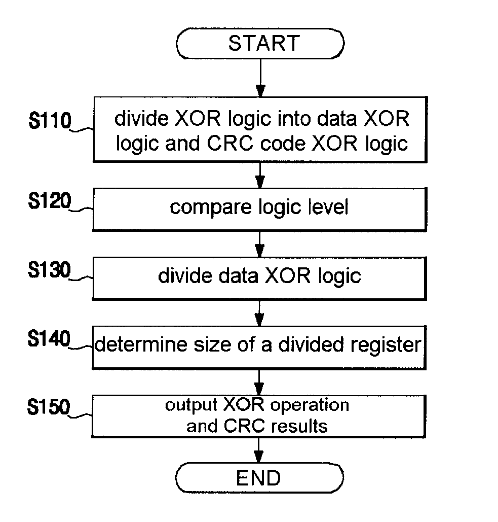
[0033] It is an object of the present invention to provide an apparatus for checking a pipelined parallel cyclic redundancy wherein, after an entire CRC (cyclic redundancy check) logic is divided into a feedback portion and an input data portion, the input data portion is divided using a pipelined structure such that the input data portion is designed to have the pipelined structure based on an algorithm that maintains a logic level of each stage to be lower than that of the feedback portion and an algorithm that optimizes a size of a register inserted during the division to improve a speed thereof and to detect an error of a received data in a high speed data communication apparatus.
[0034] It is an object of the present invention to provide a method for checking a pipelined parallel cyclic redundancy wherein, after an entire CRC (cyclic redundancy check) logic is divided into a feedback portion and an input data portion, the input data portion is divided using a pipelined structure such that the input data portion is designed to have the pipelined structure based on an algorithm that maintains a logic level of each stage to be lower than that of the feedback portion and an algorithm that optimizes a size of a register inserted during the division to improve a speed thereof and to detect an error of a received data in a high speed data communication apparatus.

Problems solved by technology

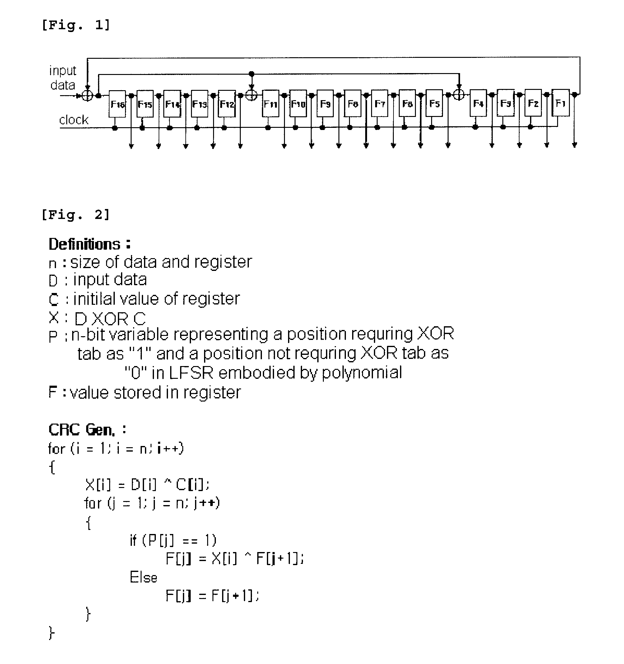
However, it is disadvantageous in that a time required for searching the table is increased as an order and a data width of a code generation polynomial are increased.
However, the conventional parallel CRC circuit is difficult to be applied to a high speed data communication since a scheme for preventing a redundancy of the circuit or reducing a logic level for using a high clock frequency is not tried.

Method used


Image

  • Method and apparatus for checking pipelined parallel cyclic redundancy
  • Method and apparatus for checking pipelined parallel cyclic redundancy
  • Method and apparatus for checking pipelined parallel cyclic redundancy

Examples


Embodiment Construction

[0043] The above-described objects and other objects and characteristics and advantages of the present invention will now be described in detail with reference to the accompanied drawings.

[0044]FIG. 5 is a diagram illustrating an apparatus for checking a pipelined parallel cyclic redundancy in accordance with the present invention.

[0045] As shown, the apparatus for checking the pipelined parallel cyclic redundancy in accordance with the present invention comprises a data XOR logic 200 including registers 210a through 210k and divided data XOR logic 220a through 220k, a CRC code XOR logic 230, a CRC register 240 and a XOR array 250.

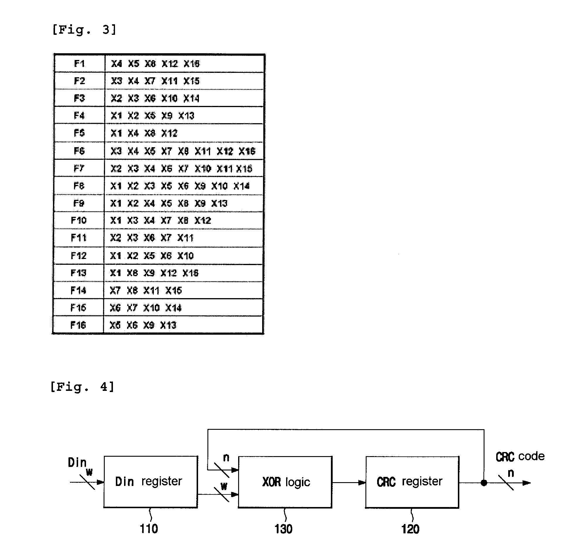
[0046] A logic level of a critical path of an XOR logic 130 of FIG. 4 is determined by a CRC when an input data bits w are equal to or smaller than a feedback CRC result bits n. However, when w is larger than n, the logic level of the critical path of the XOR logic 130 is determined by the input data since a magnitude of the input data is larger than th...


PUM


Abstract

A method and an apparatus for checking a pipelined parallel cyclic redundancy is disclosed. In accordance with the method and the apparatus of the present invention, after an entire CRC (cyclic redundancy check) logic is divided into a feedback portion and an input data portion, the input data portion is divided using a pipelined structure such that the input data portion is designed to have the pipelined structure based on an algorithm that maintains a logic level of each stage to be lower than that of the feedback portion and an algorithm that optimizes a size of a register inserted during the division to improve a speed thereof and to detect an error of a received data in a high speed data communication apparatus.

Description

RELATED APPLICATIONS [0001] The present disclosure relates to subject matter contained in priority Korean Application No. 10-2005-0133449, filed on 29 Dec. 2005 which is herein expressly incorporated by reference in its entirety. BACKGROUND OF THE INVENTION [0002] 1. Field of the Invention [0003] The present invention relates to a method and an apparatus for checking a pipelined parallel cyclic redundancy, and in particular, to a method and an apparatus for checking a pipelined parallel cyclic redundancy wherein, after an entire CRC (cyclic redundancy check) logic is divided into a feedback portion and an input data portion, the input data portion is divided using a pipelined structure such that the input data portion is designed to have the pipelined structure based on an algorithm that maintains a logic level of each stage to be lower than that of the feedback portion and an algorithm that optimizes a size of a register inserted during the division to improve a speed thereof and t...

Claims


Application Information

Patent Timeline
Patent Type & Authority Applications(United States)
IPC IPC(8): H03M13/09
CPCH03M13/6575H03M13/091G06F11/08
Inventor JEON, KI-MANPARK, CHANG-WONKIM, YOUNG-HWANKIM, KI-TAEYI, HYUN-BEANPARK, SUNG-JU
Owner KOREA ELECTRONICS TECH INST
Why Eureka
Eureka Blog
Learn More