Noise reduction device, noise reduction method, noise reduction program, and recording medium

a noise reduction and noise reduction technology, applied in the field of noise reduction devices, noise reduction methods, noise reduction programs, and recording media, can solve the problems of thermal noise, digital camera noise, and degradation of image quality, and achieve the effects of reducing noise, reducing non-additive noise in color images, and high accuracy

Active Publication Date: 2011-11-10
RICOH KK
View PDF5 Cites 26 Cited by
  • Summary
  • Abstract
  • Description
  • Claims
  • Application Information

AI Technical Summary

Benefits of technology

[0013]The present invention has been made in view of the above problems in the related arts and may provide a noise reduction apparatus and a noise reduction method for reducing noise while preserving significant elements such as an edge with which humans perceive images, preserving a signal having a small amplitude, and reducing non-additive noise in color images with high accuracy and at a low processing cost. Also, the present invention may provide a program and a recording medium used therefor.

Problems solved by technology

Images picked up by image pick-up equipment such as scanners and digital cameras contain noise such as dark current noise, thermal noise, and shot noise due to the characteristics of image pick-up devices and circuits.
If the noise is reduced simply by the use of a low-pass filter, however, significant elements such as an edge with which humans perceive images are lost at the same time, which results in degradation of image quality.
However, the c-filter and the bilateral filter have a problem in that signal components of a background part having a small amplitude are likely to be lost.
However, even the method described in Patent Document 3 cannot deal with non-additive noise such as shot noise, and it is poor in noise reduction performance with respect to color images.
Meanwhile, there has been proposed a technology for reducing non-additive noise in color images (see, for example, Non-Patent Document 3), but this method requires an enormous processing cost for segmenting images and calculating a statistics value.

Method used


Image

  • Noise reduction device, noise reduction method, noise reduction program, and recording medium
  • Noise reduction device, noise reduction method, noise reduction program, and recording medium
  • Noise reduction device, noise reduction method, noise reduction program, and recording medium

Examples


first embodiment

[0038]This embodiment refers to a noise reduction device 100 that reduces non-additive noise, whose intensity depends on a signal value, in color images where each pixel has three components of R, G, and B. In the following description, a signal value is called a pixel value as occasion demands. The noise reduction device 100 of this embodiment can preferably be applied to digital cameras, scanners, and mobile phones with cameras so long as they pick up color images. In addition, noise reduction processing of this embodiment can be applied to color images read out from storage media by computers and acquired via networks.

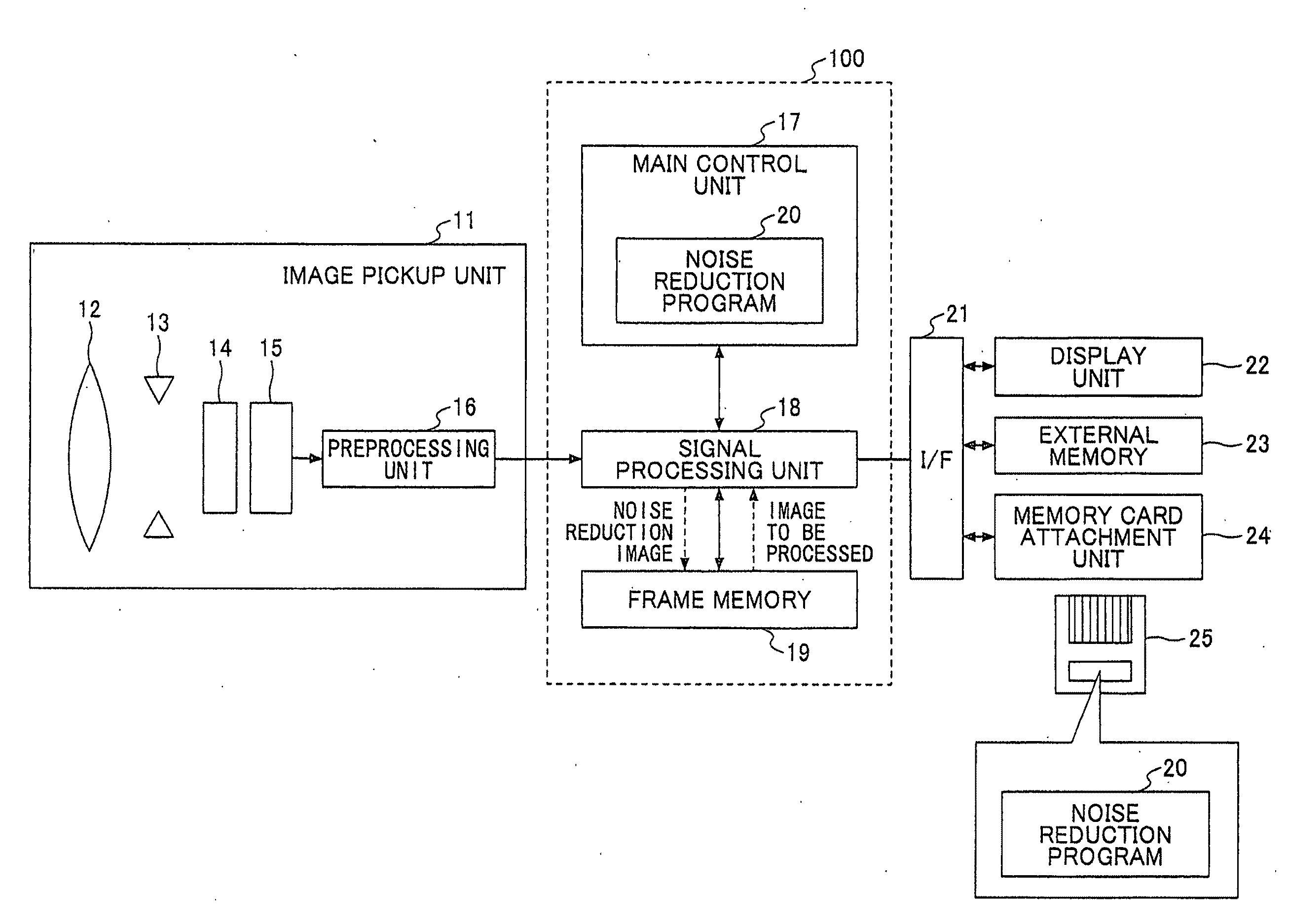
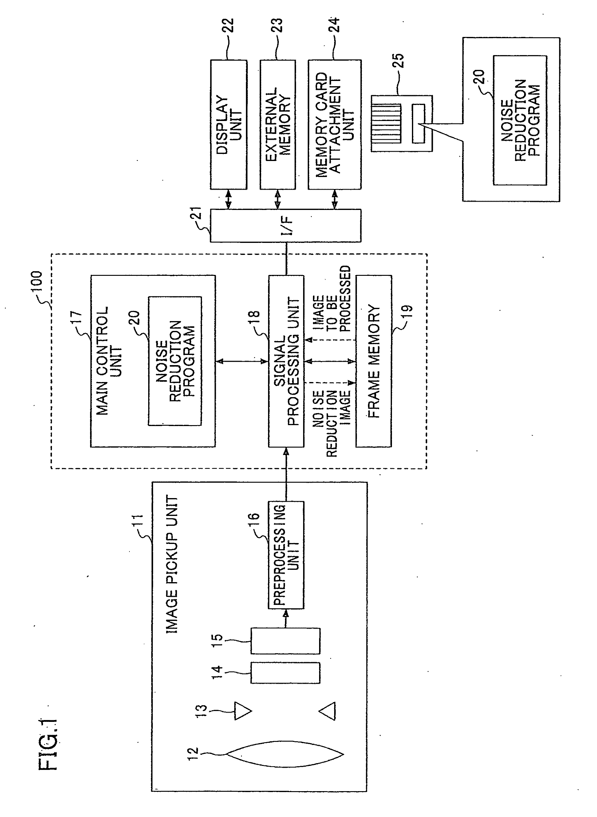
[0039]FIG. 1 shows an example of a schematic configuration diagram of a digital camera. The configuration of the digital camera may be of a typical type. The digital camera has, for example, an image pickup unit 11 that picks up images; a signal processing unit 18 that applies processing to image signals acquired from the image pickup unit 11; a main control unit 17...

second embodiment

[0102]In the first embodiment, the difference vector s is projected in the specific direction e and added to the average-value vector μ of the similarity region. In this embodiment, when an average constant RGB ratio direction of the similarity region is used as the specific direction e, the specific direction e is the same as the direction of the average-value vector μ of the pixels of the similarity region.

[0103]FIG. 10A shows a relationship between the specific direction e and the constant RGB ratio direction. In other words, the direction of the average-value vector μ coincides with the specific direction e. Accordingly, the processing of projecting the difference vector s in the constant RGB ratio direction and adding the same to the average-value vector μ of the pixels of the similarity region is equivalent to the processing of multiplying the average-value vector μ by a scalar.

[0104]Based on this fact, this embodiment refers to the noise reduction device 100 that substitutes ...

second embodiments

Equivalence between First and Second Embodiments

[0113]In the second embodiment, it is described that when the constant RGB ratio direction is used as the specific direction e, the multiplication of the average-value vector μ of the similarity region by the multiplication number η is equivalent to the processing of projecting the difference vector s in the specific direction e and adding the same to the average-value vector μ of the similarity region. A reason for this equivalency between them is described below.

[0114]The processing of the first embodiment can be expressed by the following formula.

f=μ+(1-v)μμTμ2(g-μ)(6)

[0115]The formula (6) represents the processing of linearly converting the difference vector “g−μ” and adding the same to μ. Note that v is explained in the formula (5).

[0116]The right side of the formula (6) can be converted as follows.

RIGHTSIDEOFFORMULA(6)=vμ+(1-v)μμTμ2g={v+(1-v)μTgμ2}μ(7)

[0117]In the formula (7), μ is multiplied by a coefficient. Furthermore, a vari...


PUM


Abstract

Disclosed is a noise reduction device that includes a representative-value vector calculation unit that extracts from the neighboring region the pixels of a similarity region having a degree of similarity, greater than or equal to a threshold, to the notice pixel in a predetermined color space and calculates a representative-value vector of the pixels of the similarity region; a difference projection unit that projects a difference vector between a notice-pixel vector of the notice pixel and the representative-value vector in a specific direction of the color space; and a pixel-value correction unit that replaces an element of a vector obtained by adding the difference vector projected in the specific direction to the representative-value vector with the pixel value of the notice pixel.

Description

TECHNICAL FIELD[0001]The present invention relates to a noise reduction apparatus and a noise reduction method for reducing noise in color images. Also, it relates to a program and a recording medium used therefor.BACKGROUND ART[0002]Images picked up by image pick-up equipment such as scanners and digital cameras contain noise such as dark current noise, thermal noise, and shot noise due to the characteristics of image pick-up devices and circuits. In order to obtain high-quality images, processing for reducing the noise described above must be performed. If the noise is reduced simply by the use of a low-pass filter, however, significant elements such as an edge with which humans perceive images are lost at the same time, which results in degradation of image quality. Accordingly, technologies for reducing the noise in accordance with the characteristics of the regions of images have been demanded.[0003]As one of such noise reduction technologies, an 6-filter has been proposed (see...

Claims


Application Information

Patent Timeline
Patent Type & Authority Applications(United States)
IPC IPC(8): G06K9/40G06K9/00
CPCG06T5/20G06T2207/10024H04N1/409H04N9/646G06T5/002H04N5/213
Inventor HARA, TAKAYUKI
Owner RICOH KK
Why Eureka
Try Eureka