Safe simple disposable automatic blood lancet

a technology of automatic ejection and lancet, which is applied in the field of medical equipment technology, can solve the problems of failure of the ejection structure of the bayonet, unusability, and failure of the blood lancet to be ejected, and achieve the effect of safer application and simple operation

Inactive Publication Date: 2011-11-10
STERILANCE MEDICAL SUZHOU
View PDF3 Cites 4 Cited by
  • Summary
  • Abstract
  • Description
  • Claims
  • Application Information

AI Technical Summary

Benefits of technology

, the present invention develops advantages of the Chinese patent CN2705119Y or the U.S. Pat. No. 7,322,997B2, and overcomes their shortcomings, making this improved product fully attain the purpose of more advanced technology, simpler operation, and safer application.

Problems solved by technology

After the ejection, because of the movement of the button, the barb moves forward beyond the self-locking opening; therefore, the barb is locked at the self-locking opening in the rebounding process, and cannot go back to the pre-ejection state, making the bayonet ejection structure fail and unreusable.
However, this will then result in a hidden trouble with the blood lancet, since even if the protective bar is not twisted off, the bayonet ejection structure may be triggered through the button during transportation and before application.
This is also the first problem with this patented product.
The second problem is that when the medical care personnel use this blood lancet for the first time, they may not read the operation instruction in detail, and may twist off the protective bar during application without pushing the protective bar first, which will also make the blood lancet fail to be ejected due to the blood lancet not being blocked into the bayonet ejection structure.

Method used


Image

  • Safe simple disposable automatic blood lancet
  • Safe simple disposable automatic blood lancet
  • Safe simple disposable automatic blood lancet

Examples


example 1

A Safe Simple Disposable Automatic Blood Lancet

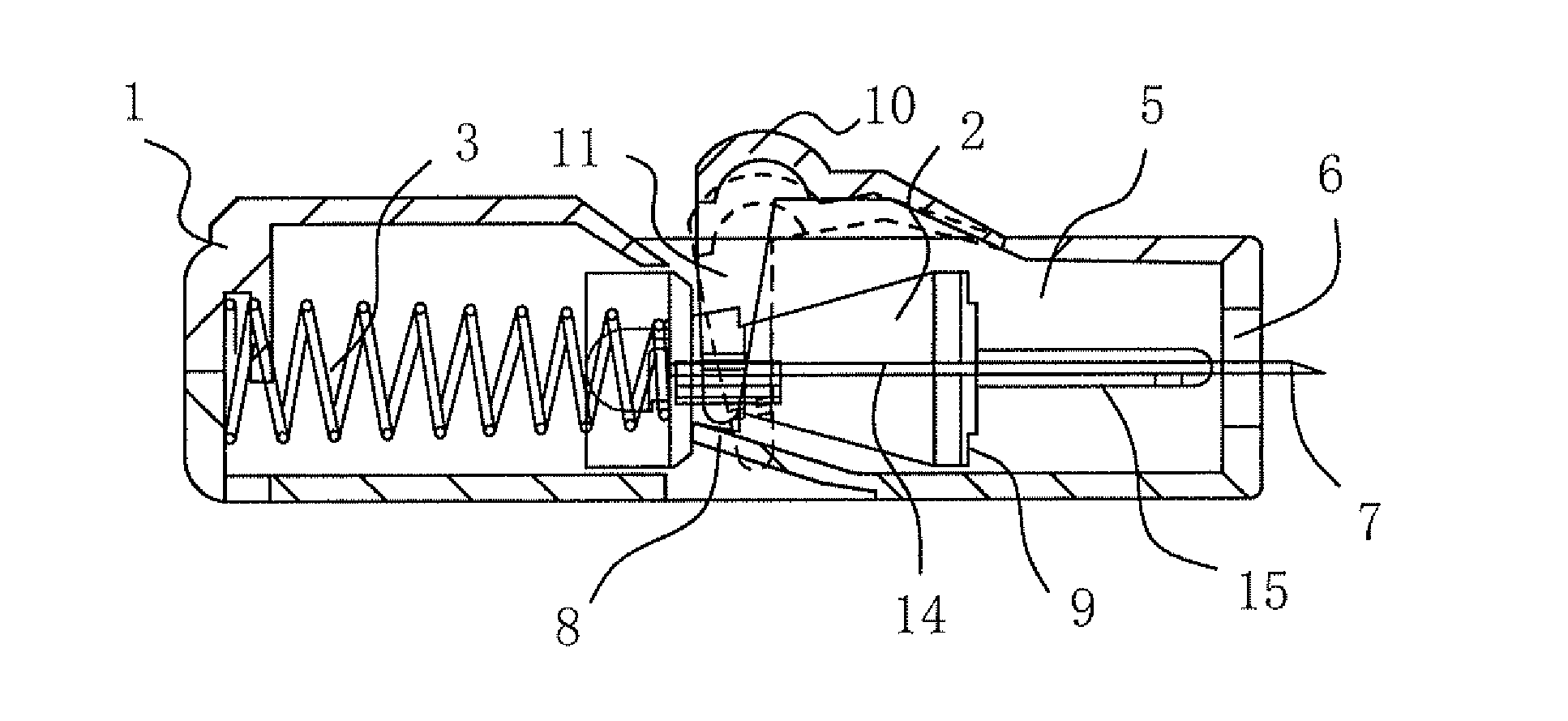
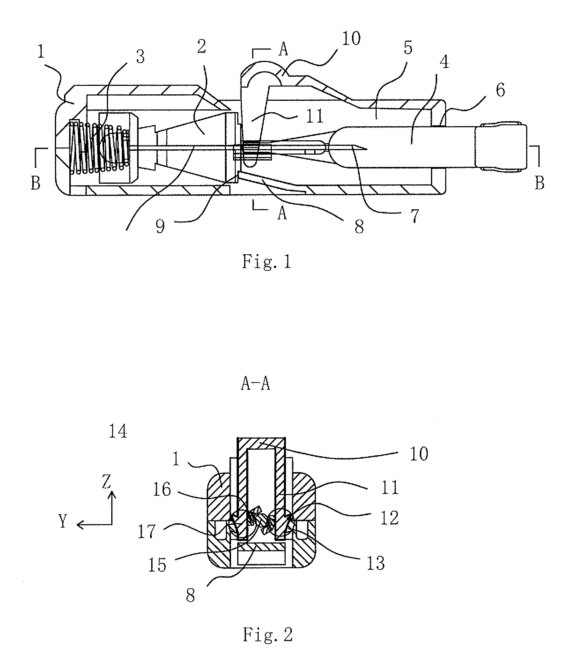
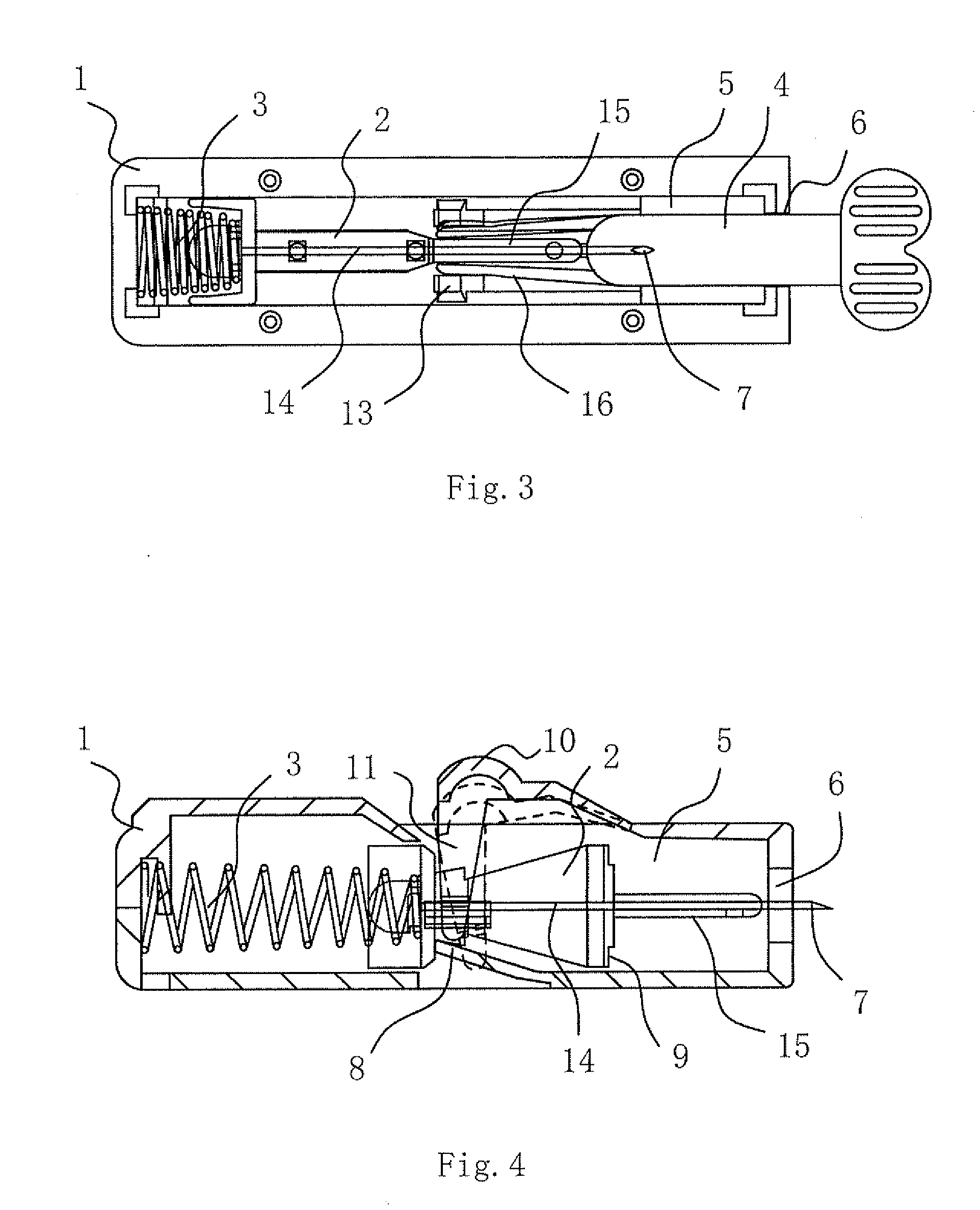
As shown in FIGS. 1-3, this blood lancet is composed of a casing 1, a lancet core 2, a spring 3 and a protective bar 4. The casing 1 is divided into two parts top and bottom, both of which are connected to form an integral structure through pin and hole structures provided on the contact surface. The casing 1 forms an ejection cavity 5, which is provided at one end with a pinhole 6. The lancet core 2 is arranged inside the ejection cavity 5 and provided at one end with a protective bar 4, one end of which is protruded out of the pinhole 6 of the casing 1. The lancet core 2 is provided inside with a needle 14, a needle point 7 of which is located inside the protective bar 4 and oriented towards the pinhole 6. The protective bar 4 and the lancet core 2 are connected by muff-coupling or via a neck 18 that can be twisted broken to enable a demountable connection. The spring 3 is arranged at the other end of the lancet core 2, thus forming a...

example 2

A Safe Simple Disposable Automatic Blood Lancet

As shown in FIGS. 12-15, this example is different from Example 1 in the following aspects: The safety action portion is arranged for the two spaces 17, and refers to one safety jacket 20 extended from the end of the protective bar 4. The safety jacket 20 is muff-coupled in front of the lancet core 2 or with the needle 14. With the protective bar 4 assembled, the external edge of the safety jacket 20 occupies the two spaces 17 in the Y direction (see the direction as indicated by the coordinate in FIG. 15) (see the area circled by the double dotted line as indicated by the reference number 17 in FIG. 15), making the widths of the two spaces 17 in the Y direction both smaller than the width at which the push arm 11 of the “U-shaped” branch structure can be inserted, so as to prevent the push arm 11 from moving downwards to drive the barb 12 to be self-locked with the self-locking barb 13. With the protective bar 4 disassembled, the safet...

example 3

A Safe Simple Disposable Automatic Blood Lancet

As shown in FIGS. 16-18, this example is different from Example 1 in the following aspects: The safety action portion is arranged for the two spaces 17, and refers to two safety wings 21 extended from the end of the protective bar 4. With the protective bar 4 assembled, the two safety wings 21 occupy the two spaces 17 in the X direction (see the direction as indicated by the coordinate in FIG. 16), making the widths of the two spaces 17 in the X direction both smaller than the width at which the push arm 11 of the “U-shaped” branch structure can be inserted, so as to prevent the push arm 11 from moving downwards to drive the barb 12 to be self-locked with the self-locking barb 13. With the protective bar 4 disassembled, the two safety wings 21 both withdraw from the two spaces 17, making the widths of the two spaces 17 in the X direction bigger than or equal to the width at which the push arm 11 of the “U-shaped” branch structure can be...


PUM


Abstract

A safe simple disposable automatic blood lancet is disclosed in the present invention, including a casing, a lancet core, a spring and a protective bar. It has the following features: The ejection cavity is provided inside with a space that allows the push arm to move downwards; the protective bar is provided at the end inside the ejection cavity with a safety action portion; with the protective bar assembled, this safety action portion occupies the space in the X, Y or Z direction, so as to prevent the barb from being self-locked with the self-locking barb with the push arm moving downwards; with the protective bar disassembled, this safety action portion withdraws from the space, so as to allow the barb to be self-locked with the self-locking barb with the push arm moving downwards. The present invention allows the lancet core to be assembled into the locking state of ready for ejection; the blood lancet can be placed into the ejection state just by twisting off the protective bar during application, and into the locking state automatically after ejection so as to be unreusable. Compared with the prior art, the present invention fully attains the purpose of more advanced technology, simpler operation, and safer application.

Description

FIELD OF THE INVENTIONThe present invention belongs to the field of medical apparatus technology, and particularly relates to a disposable automatic blood lancet. This blood lancet can be used simply after just twisting off the protective bar; and it can be placed into a self-locking state after ejection by locking the button through the casing engaged with the button, thus attaining the purpose of making the blood lancet unreusable.BACKGROUND OF THE INVENTIONThe disposable automatic blood lancet, as the main development stream of the current blood lancet, has been improved and developed constantly for many years. The Chinese patent once announced on Tune 22, 2005 to authorize a utility model patent titled “Casing Self-Locking Disposable Safe Automatic Blood Lancet” with a patent number of 200420026368.7 and an announcement number of CN2705119Y (with this patent enjoying the right of priority, an American patent is applied for afterwards with a patent number of U.S. Pat. No. 7,322,9...

Claims


Application Information

Patent Timeline
Patent Type & Authority Applications(United States)
IPC IPC(8): A61B17/32
CPCA61B5/15142A61B5/1411A61B5/150022A61B5/150412A61B5/150511A61B5/150519A61B5/150549A61B5/150618A61B5/150717A61B5/150916A61B5/15113A61B5/15117
Inventor SHI, GUOPING
Owner STERILANCE MEDICAL SUZHOU
Why Eureka
Try Eureka