
Method of damping the vibrations of stay cables and associated system

Active Publication Date: 2011-11-17
SOLETANCHE FREYSSINET SA
View PDF6 Cites 19 Cited by
  • Summary
  • Abstract
  • Description
  • Claims
  • Application Information

AI Technical Summary

Benefits of technology

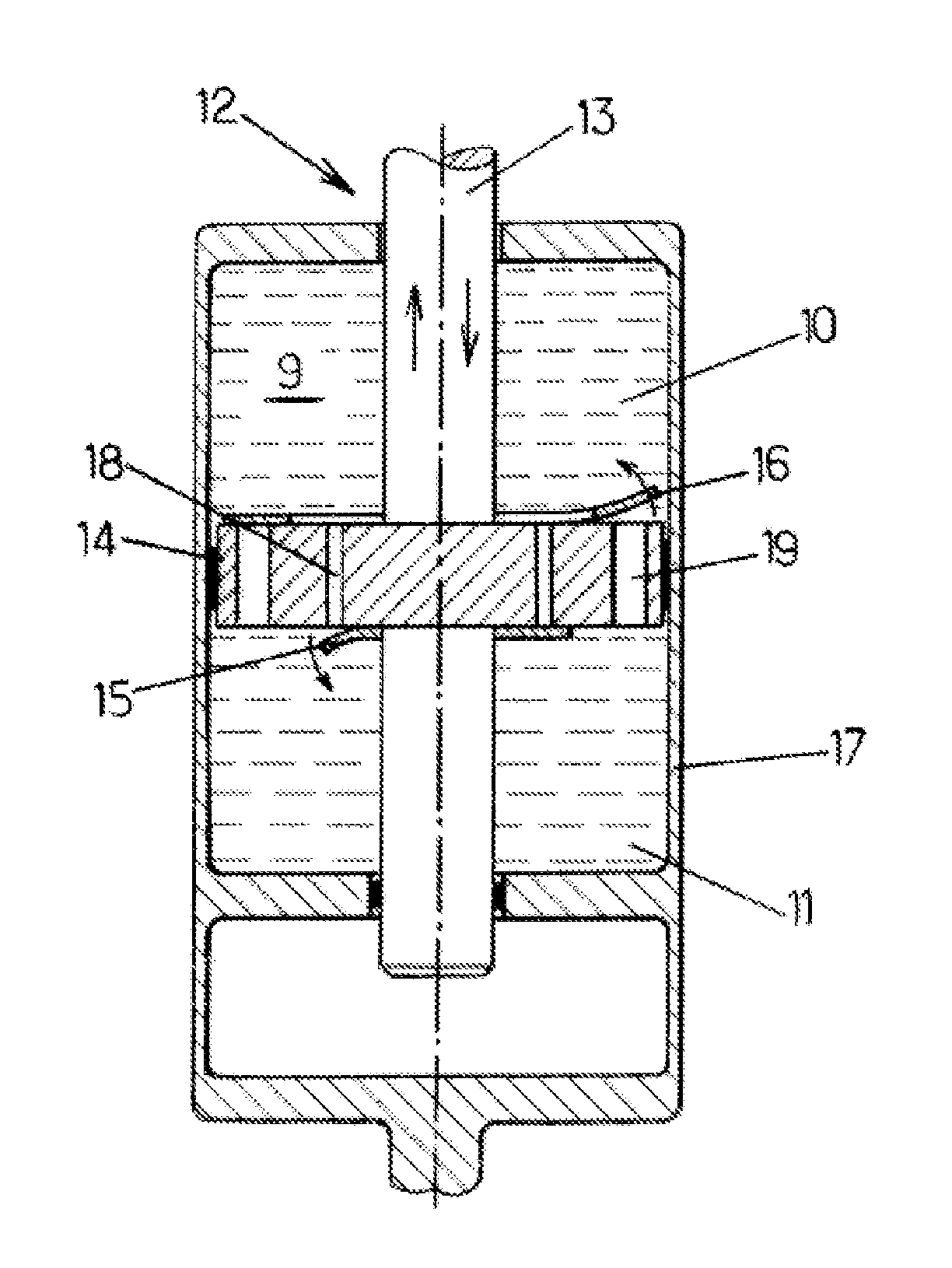
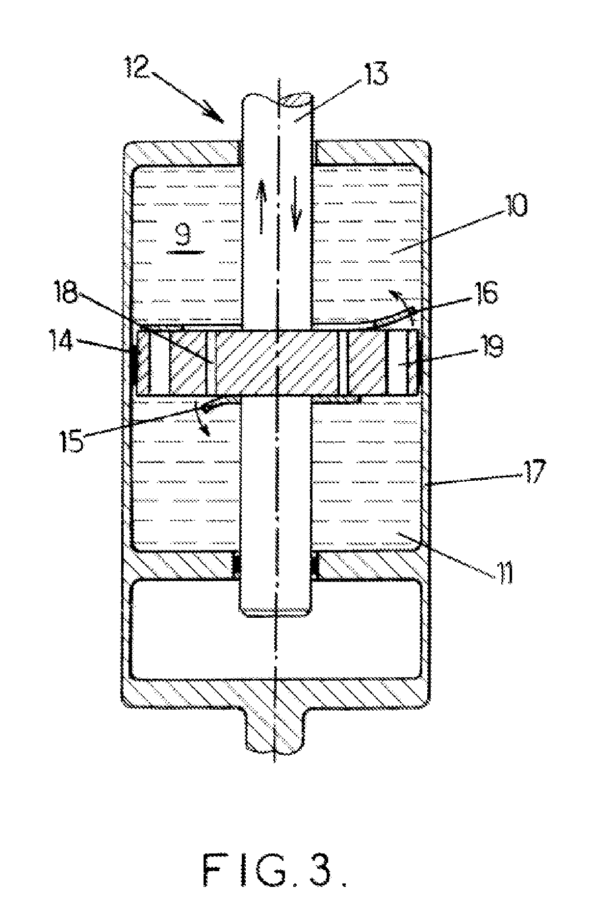
[0021]The use of a damper makes it possible to limit at least some of the drawbacks of the above-mentioned interconnecting cables. Moreover the difference in stiffness under tension and compression of the damper makes it possible to limit at least some of the drawbacks of the above-mentioned symmetrical dampers.
[0026]the pressure difference created by the passage of the fluid is less when the damper is working under compression in comparison with its working under tension;
[0032]the connection between the damper and at least one of the stay cables of said pair allows said stay to rotate about the axis;

Problems solved by technology

However, under certain conditions, in particular when the bridge deck undergoes periodic excitations, the stay cables can build up energy and vibrate significantly.
The two main causes of these vibrations are the movement of the stay cable anchors with respect to the deck under the effect of traffic loads, and the effect of the wind acting directly on the stay cables.
When uncontrolled, such vibrations are capable of directly damaging the stay cables, while being a source of anxiety to users present on the bridge deck.
Taking into account these different parameters thus complicates to a relatively significant extent the installation of the interconnecting cables in order to stiffen the stay cable array of a civil engineering structure.
Moreover, when such interconnecting cables must be installed after the commissioning of the civil engineering structure, in order for example to correct stability problems, it is essential as described above to pre-tension the set of interconnecting cables, which therefore alters the geometry of the different stay cables of the stay cable array, with consequences for the structure of the construction and in particular the appearance of angular fractures at the level of the ends of the stay cables directly anchored on the pylon and on the bridge deck in the case of cable-stayed bridges.
However, when operating under compression, the reaction force of the piston can be a source of instability.
When two dampers on either side of a stay cable are compressed, the stay cable held between these two elements risks being pushed outside the plane of the array.
This instability means that the dampers no longer work.

Method used


Image

  • Method of damping the vibrations of stay cables and associated system
  • Method of damping the vibrations of stay cables and associated system
  • Method of damping the vibrations of stay cables and associated system

Examples


Embodiment Construction

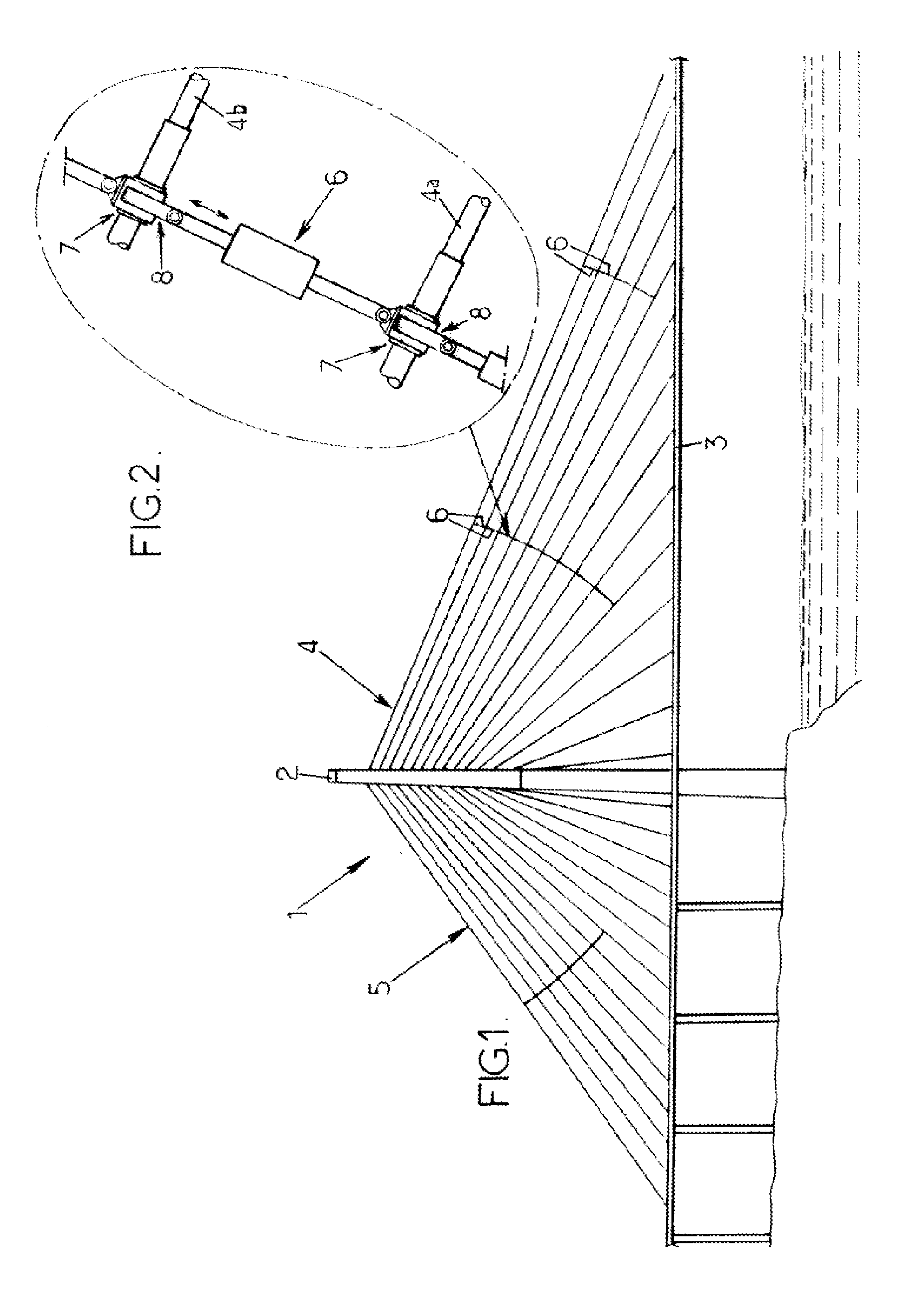
[0045]The invention relates to damping the vibrations of at least one pair of stay cables of a civil engineering structure. The case will be considered below in which the vibrations of at least two stay cables of a cable-stayed bridge are damped. This example is however given by way of illustration only and in no way limits the general scope of the invention. By way of an alternative example of a civil engineering structure including at least two stay cables, to which the present invention can be applied, a building, a column capital, or other can be mentioned.

[0046]FIG. 1 shows a cable-stayed bridge 1 that comprises at least one pylon 2, a deck 3 and, in the example considered here, two stay cable arrays 4 and 5 that connect the deck 3 to the pylon 2.

[0047]The stay cable arrays 4 and 5 are used to support the portion of the deck 3 that does not rest on supporting pylons (portion of the deck located to the right of the pylon 2 in the example considered here).

[0048]The stay cable arr...


PUM


Abstract

Method of damping the vibrations of at least one pair of stay cables (4a, 4b) of a civil engineering structure (1), in which the stay cables of said pair are linked by a damper (6) having a first stiffness in response to tensile stress and a second stiffness in response to compressive stress, the first stiffness being greater than the second stiffness.

Description

CROSS-REFERENCE TO RELATED APPLICATION[0001]This application claims the benefit under 35 U.S.C. §119(e) of Russian Patent Application No. 2010119171 filed May 12, 2010, which application is incorporated herein by reference in its entirety.BACKGROUND OF THE INVENTION[0002]The present invention relates to damping the vibrations of at least two stay cables of a civil engineering structure.[0003]By way of non-limitative example, the damping proposed by the invention can in particular serve to damp the vibrations of a stay cable array of a cable-stayed bridge. In cable-stayed bridges, the stay cables forming the stay cable array are generally anchored at their upper end on a pylon and at their lower end on the bridge deck. The stay cable array thus ensures the support and stability of the structure.[0004]However, under certain conditions, in particular when the bridge deck undergoes periodic excitations, the stay cables can build up energy and vibrate significantly. The two main causes o...

Claims


Application Information

Patent Timeline
IPC IPC(8): F16F9/19E01D11/04E01D19/16F16F9/50
CPCE01D19/16E01D11/04
Inventor STUBLER, JEROMEMELLIER, ERIK
Owner SOLETANCHE FREYSSINET SA
Learn More