Gate hugger - platform and loading ramp system

a platform and platform technology, applied in the direction of loading/unloading, bridges, construction, etc., can solve the problems of increased problem, increased weight, and unsafe practice of many types of loading ramps, and achieve the effect of a higher degree of safety

Inactive Publication Date: 2011-11-17
BILLOW HARRY JAMES
View PDF5 Cites 1 Cited by
  • Summary
  • Abstract
  • Description
  • Claims
  • Application Information

AI Technical Summary

Benefits of technology

[0006]To manufacture an anchoring source for ramps; therefore to establish a higher degree for safety in loading motorbikes, ATVs, etc., the design of the Gate Hugger Platform is developed.

Problems solved by technology

Experience loading and unloading motorbikes, ATVs, etc. has proven to be an unsafe practice with many types of loading ramps.
Accidents occur when the loading ramps are not secured to the vehicle allowing them to give way during the loading process.
The shifting of weight in maneuvering the motorbike, shifting of weight due to uneven surfaces at the base of the ramp, and environmental conditions develop problems at the anchor points of loading ramps.
This problem is greatly enhanced when the anchor point at the tailgate / ramp location is a metal surface placed against another poor gripping surface.

Method used


Image

  • Gate hugger - platform and loading ramp system
  • Gate hugger - platform and loading ramp system

Examples


Embodiment Construction

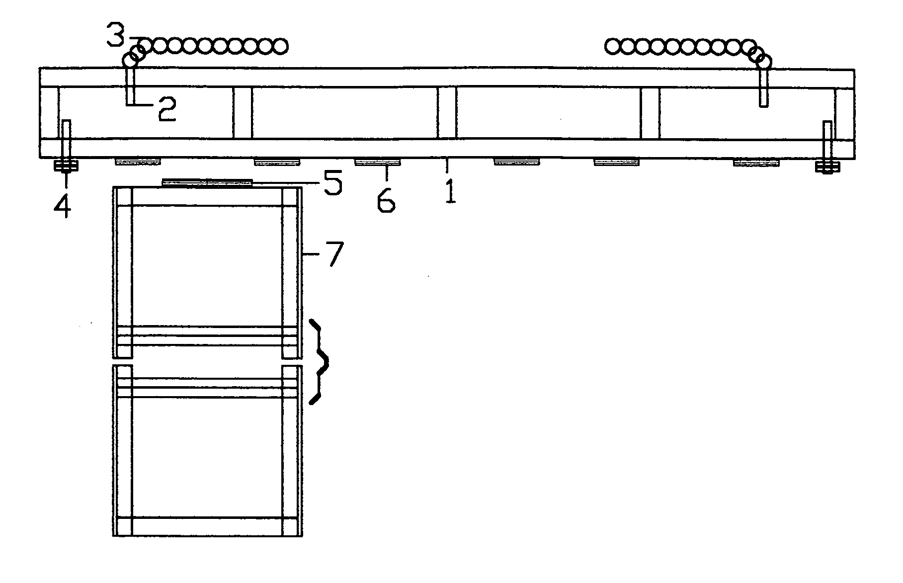
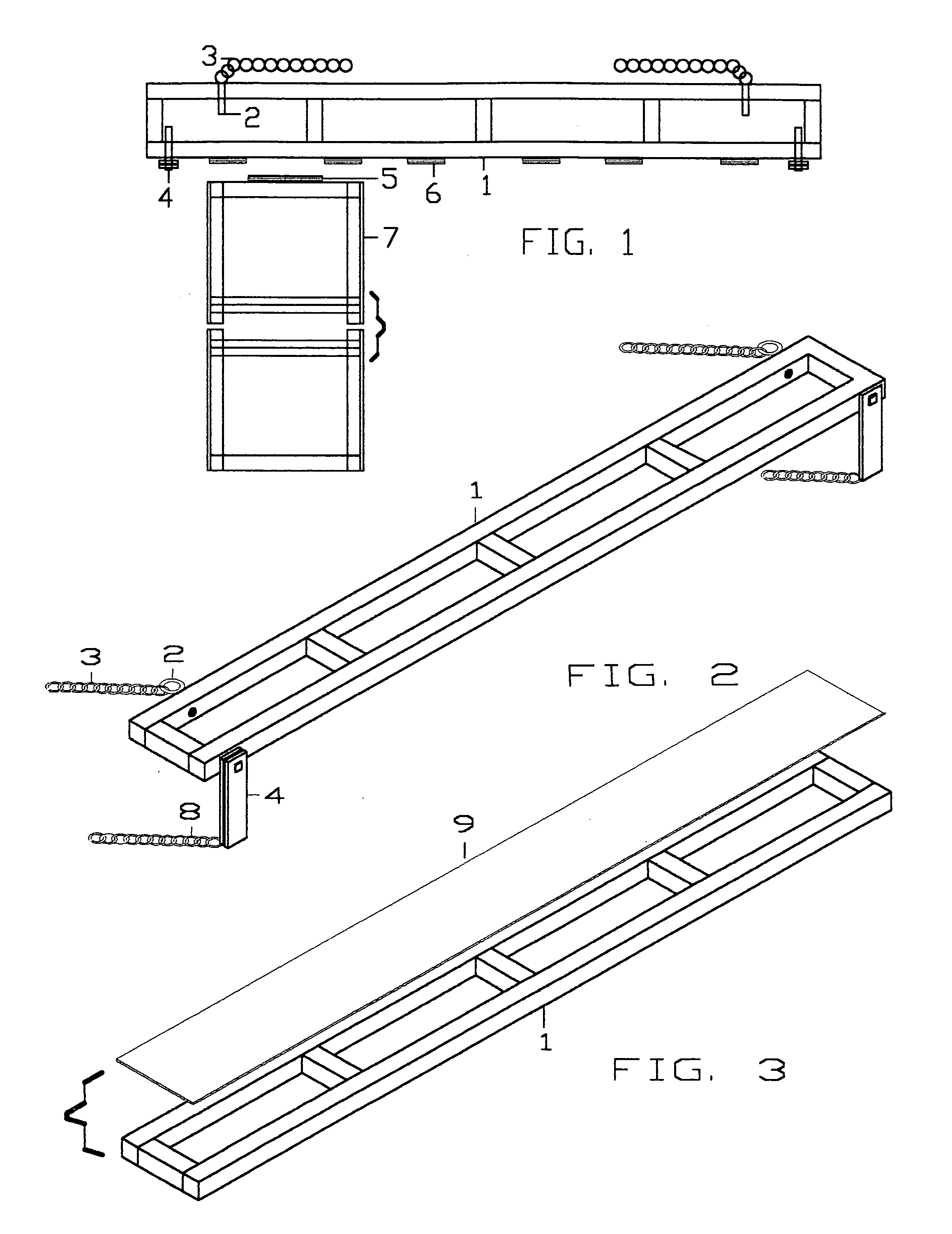
[0028]The Gate Hugger platform and ramp system is developed to improve safety in the loading and unloading process of motorbikes, ATVs, etc. It is a new concept allowing for the securing of a loading ramp to the conventional tailgate of a pickup without making alterations to or damage to the tailgate. The Gate Hugger also improves the versatility of loading ramps by allowing safe and secure use of ramps at angles (plus and minus) to the plane of the tailgate unlike many ramps produced to this date.

[0029]The frame of the Gate Hugger platform is constructed of 1¼ steel channel. Two 54 inch lengths of channel are welded to 3½ inch lengths at the ends, center, and two locations half the distance from center to ends to form a rectangle 54 inches by 6 inches. A cover plate of ⅛ inch steel plate of the same dimension, 54 inches by 6 inches is welded to one (top) side of the frame.

[0030]Located 6 inches in from both ends at the front of the platform are two ½ inch eyebolts. The frame is dri...


PUM


Abstract

1. A securing platform comprising:
    • a reinforced rectangular frame and cover plate; the longest length runs parallel and rests upon the top of an open tailgate of a pickup,
    • an eyebolt located 6 inches in from both ends of front face of platform; with attached securing chains to be anchored to tiedowns at rear of truck bed,
    • a metal plate and a rubber pad are bolted 1⅝ inches in from both ends to the rear face of platform to hang 90 degrees below the horizontal plane of tailgate to function as stop from forward motion; a securing chain attached to the opposite end of each metal plate is anchored to the bumper of a pickup truck,
    • steel tubing is welded to the rear face of the platform to form outside portions of a hinge and configured to attach ramps at three locations;
2. Loading ramps comprising:
  • 1¼ inch steel square channel on the end; 1½ inch angle steel for six and eight foot sides, with 1 foot cross members spaced 10 inches apart,
  • wherein a steel tube is centered and welded to the end of a ramp to form the center portion of a hinge connection,
  • wherein loading ramps are attached to the platform by inserting a solid 1/4 inch steel rod through the three portions of steel tubing; therefore securing the ramp and allowing the ramp to pivot at various degrees from the plain of the tailgate.
  • Description

    CROSS-REFERENCE TO RELATED APPLICATIONS[0001]“Not Applicable”STATEMENT REGARDING FEDERALLY SPONSORED RESEARCH OR DEVELOPMENT[0002]“Not Applicable”REFERENCE TO SEQUENCE LISTING, A TABLE, OR A COMPUTER PROGRAM LISTING COMPACT DISC APPENDIX[0003]“Not Applicable”BACKGROUND OF THE INVENTION[0004]Experience loading and unloading motorbikes, ATVs, etc. has proven to be an unsafe practice with many types of loading ramps. Accidents occur when the loading ramps are not secured to the vehicle allowing them to give way during the loading process. Most loading ramps rely on the weight of the motorbike plus the pressure against the tailgate to secure the ramp for the loading or unloading process. The shifting of weight in maneuvering the motorbike, shifting of weight due to uneven surfaces at the base of the ramp, and environmental conditions develop problems at the anchor points of loading ramps. This problem is greatly enhanced when the anchor point at the tailgate / ramp location is a metal sur...

    Claims


    Application Information

    Patent Timeline
    Patent Type & Authority Applications(United States)
    IPC IPC(8): B65G69/30
    CPCB65G69/30
    Inventor BILLOW, HARRY JAMES
    Owner BILLOW HARRY JAMES
    Why Eureka
    Try Eureka