
Superconducting motor

a superconducting motor and superconducting technology, applied in the direction of indirect heat exchangers, air heaters, light and heating apparatus, etc., can solve the problems of difficult uniform cooling, large circumferential and axial temperature gradients, and take a long time to cool all the coils to the target ultralow temperature, etc., to achieve the effect of cooling the phase coils down

Inactive Publication Date: 2011-11-17
TOYOTA JIDOSHA KK +1
View PDF12 Cites 6 Cited by
  • Summary
  • Abstract
  • Description
  • Claims
  • Application Information

AI Technical Summary

Benefits of technology

[0010]The invention provides a superconducting motor that is capable of cooling a plurality of phase coils, each formed of a superconducting wire, down to a desired ultralow temperature efficiently and promptly.
[0012]According to the above aspect, because the cooling portion of the refrigerator is in contact with the phase coils and therefore the phase coils, each formed of the superconducting wire, are directly cooled, not via the stator core, or the like, it is possible to cool the phase coils down to a desired ultralow temperature efficiently, and promptly.

Problems solved by technology

However, in a case where the stator coils of a superconducting motor are cooled using a refrigerator, if the coils that are formed of superconducting wires are cooled to a target ultralow temperature via other member(s) having a large heat capacity, such as a stator core, it takes much time to cool all the coils to the target ultralow temperature.
In addition, in a structure in which, for cooling, the cooling portion of a refrigerator is in contact with only a portion of the outer peripheral face of the stator core, it is difficult to evenly cool the portions of the stator core that are radially opposed to the cooled portion of the stator core and the coils that are provided at the same portions of the stator core, and thus large circumferential and axial temperature gradients may occur depending upon the thermal conductivities of the respective portions.

Method used


Image

  • Superconducting motor
  • Superconducting motor
  • Superconducting motor

Examples


first embodiment

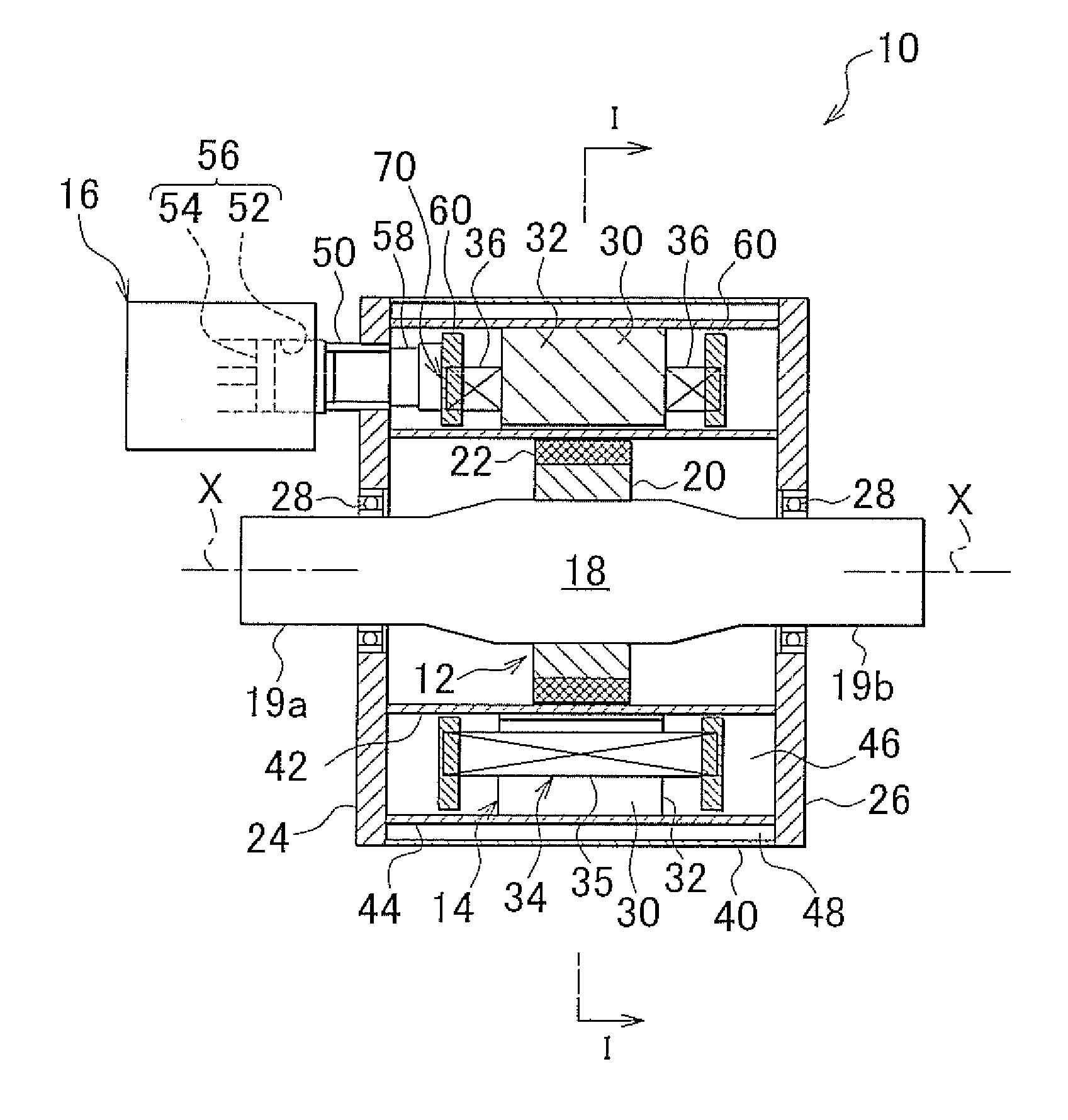
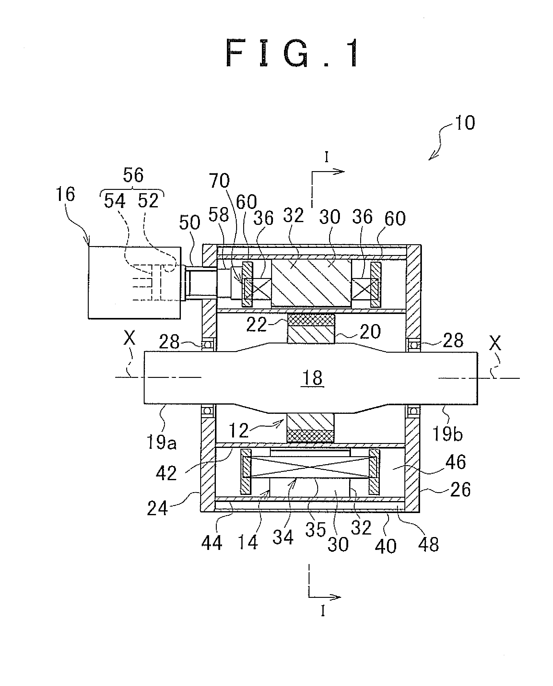
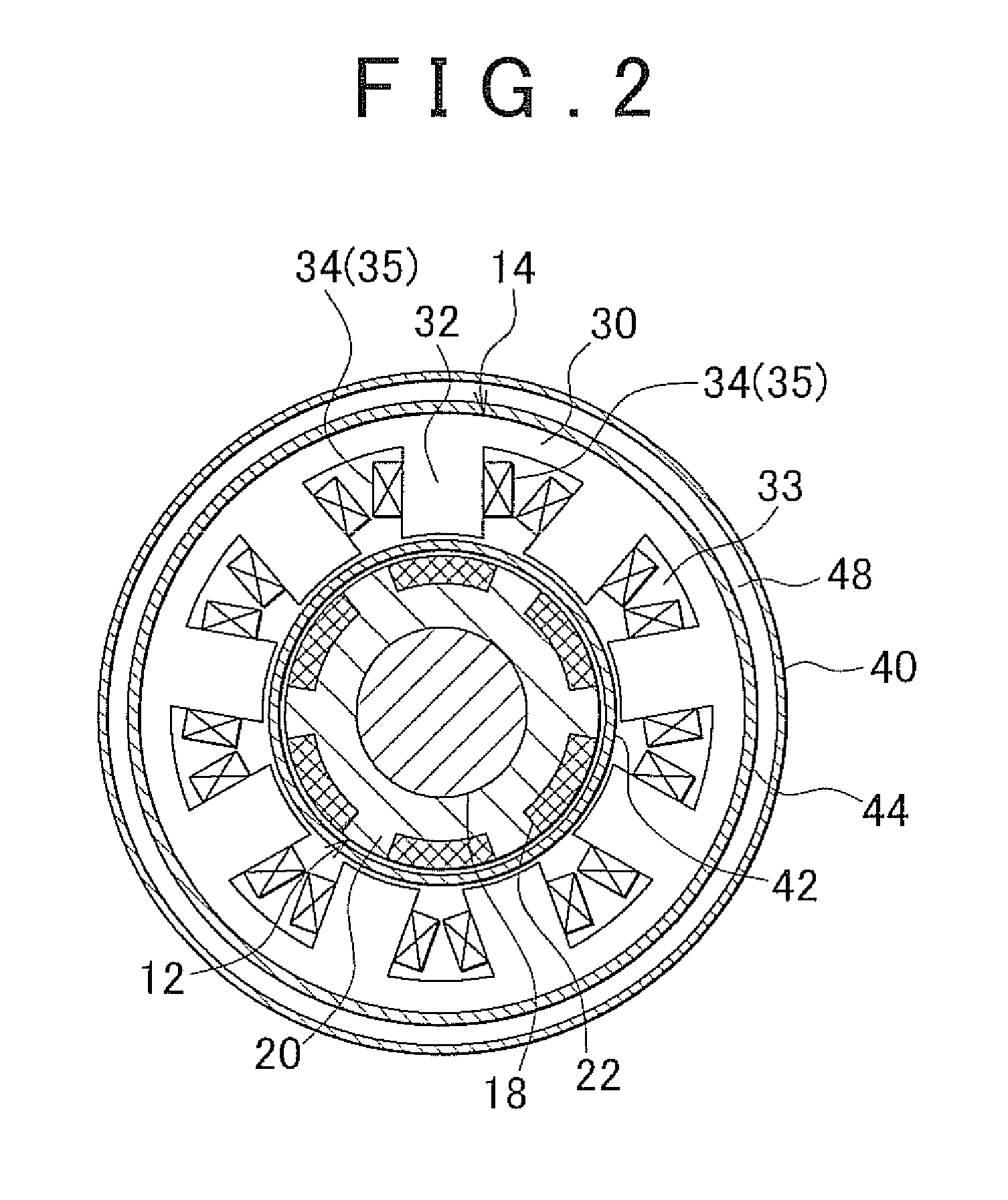
[0031]FIG. 1 is a sectional view of a superconducting motor 10 showing the invention, which is taken along the axial direction of the superconducting motor 10, and which also shows part of the side faces of the superconducting motor 10. FIG. 2 is a sectional view of the superconducting motor 10 that is taken along the line I-I shown in FIG. 1 (note that the hatching of the stator core is omitted in this view). The superconducting motor 10 has a rotor 12 that is rotatably supported, a stator 14 that is generally cylindrical and is arranged so as to surround the outer periphery of the rotor 12, and a refrigerator 16 that is fixed on an axial end face of the superconducting motor 10. Note that, in the following descriptions on the respective example embodiments, each direction that extends along a rotational axis X of a rotor shaft 18 that passes through the center of the rotor 12 will be referred to as “axial direction (motor-axis direction)”, each radial direction intersecting the ro...

second embodiment

[0074]FIG. 10 shows a sectional view of the superconducting motor 10a of the second embodiment that is taken along the axial direction thereof and also shows the side faces of some portions of the superconducting motor 10a. FIG. 11 is a view schematically illustrating an electric connection in the superconducting motor 10a, shown in FIG. 10, in which the phase coils 34U, 34V, and 34W are connected to each other at two neutral points 70a and 70b.

[0075]The superconducting motor 10a of the second embodiment has a refrigerator 17 in addition to the refrigerator 16. In the following descriptions, the refrigerators 16 and 17 will be referred to as “the first refrigerator 16” and “the second refrigerator 17”, respectively. The second refrigerator 17 is attached to the endplate 26 located at the other axial side via a structure that is the same as that for the refrigerator 16.

[0076]The first refrigerator 16 and the second refrigerator 17 are arranged so as to face each other such that the ...


PUM


Abstract

A superconducting motor includes: a rotor that is rotatably supported; a stator that is provided around the rotor, and that is provided with a plurality of coils that are respectively formed of superconducting wires and that are wound at an inner periphery of a stator core; and a refrigerator having a cooling portion for cooling the plurality of coils. The cooling portion of the refrigerator is in contact with the plurality of coils.

Description

CROSS-REFERENCE TO RELATED APPLICATIONS[0001]This application claims priority to Japanese Patent Application No. 2010-112094 filed on May 14, 2010, which is incorporated herein by reference in its entirety including the specification, drawings and abstract.BACKGROUND OF THE INVENTION[0002]1. Field of the Invention[0003]The invention relates to a superconducting motor, and especially to a superconducting motor that is provided with a refrigerator for cooling coils that are formed of superconducting wires.[0004]2. Description of the Related Art[0005]Recently, much attention has been paid to electric motor vehicles (will hereinafter be referred to as “EVs”) that run on the drive force produced by an in-vehicle motor powered by an in-vehicle secondary battery, thus emitting no carbon dioxides, that is, achieving “zero emissions”. Further, hybrid electric motor vehicles (will hereinafter be referred to as “HEVs”) that run using, as drive force sources for propelling the vehicle, both an ...

Claims


Application Information

Patent Timeline
IPC IPC(8): F28D21/00F25B1/00
CPCH02K55/02H02K9/22H02K9/223
Inventor MIZUTANI, RYOJIOHASHI, YOSHIMASAOKUMURA, NOBUOISHIDA, KENJI
Owner TOYOTA JIDOSHA KK
Learn More