Rotor or a stator for a superconducting electrical machine

a superconducting electrical machine and rotor technology, applied in the direction of dynamo-electric machines, electrical apparatus, magnetic circuits, etc., can solve the problems of short circuit torque, large contractive force that the rotor or stator must withstand, oscillatory and typically many times greater torque, etc., to minimize their thermal expansion and contraction, low thermal conductivity, and low cost

Inactive Publication Date: 2014-04-08
GE ENERGY POWER CONVERSION TECH
View PDF9 Cites 6 Cited by
  • Summary
  • Abstract
  • Description
  • Claims
  • Application Information

AI Technical Summary

Benefits of technology

[0015]Preferably the, or each, coupling element is also designed to minimize the heat flow from the mounting to the field coil support structure during operation of the electrical machine. This is in order to minimize the amount of cooling required to maintain the field coil support structure and the field coils at cryogenic temperatures.
[0032]When under tensile stress, coupling elements formed as linear struts will act in substantially the same manner as tie rods. When under compressive stress, the coupling elements will act as bracing struts. To improve the capability of the coupling elements to act as bracing struts and withstand compressive forces they may be pre-tensioned. As will be understood by those skilled in the art, pre-tensioning may be applied to the coupling elements either during assembly of the rotor at ambient temperatures, or during cooling of the field coil support structure to cryogenic temperatures.

Problems solved by technology

This includes short circuit torque, which is oscillatory and is typically many times greater than normal rated torque.
This cooling produces large contractive forces which the rotor or stator must withstand.

Method used


Image

  • Rotor or a stator for a superconducting electrical machine
  • Rotor or a stator for a superconducting electrical machine
  • Rotor or a stator for a superconducting electrical machine

Examples


Embodiment Construction

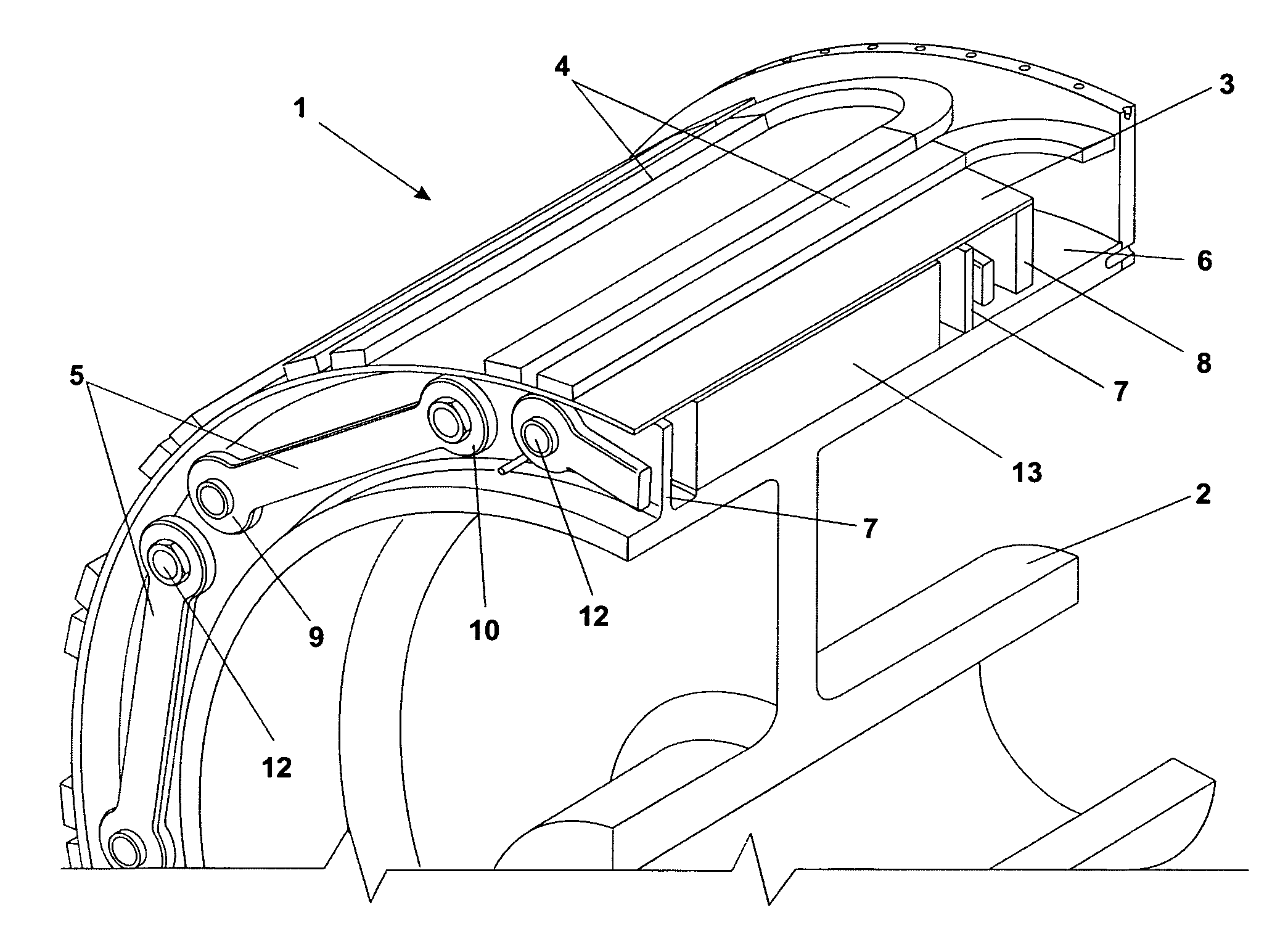
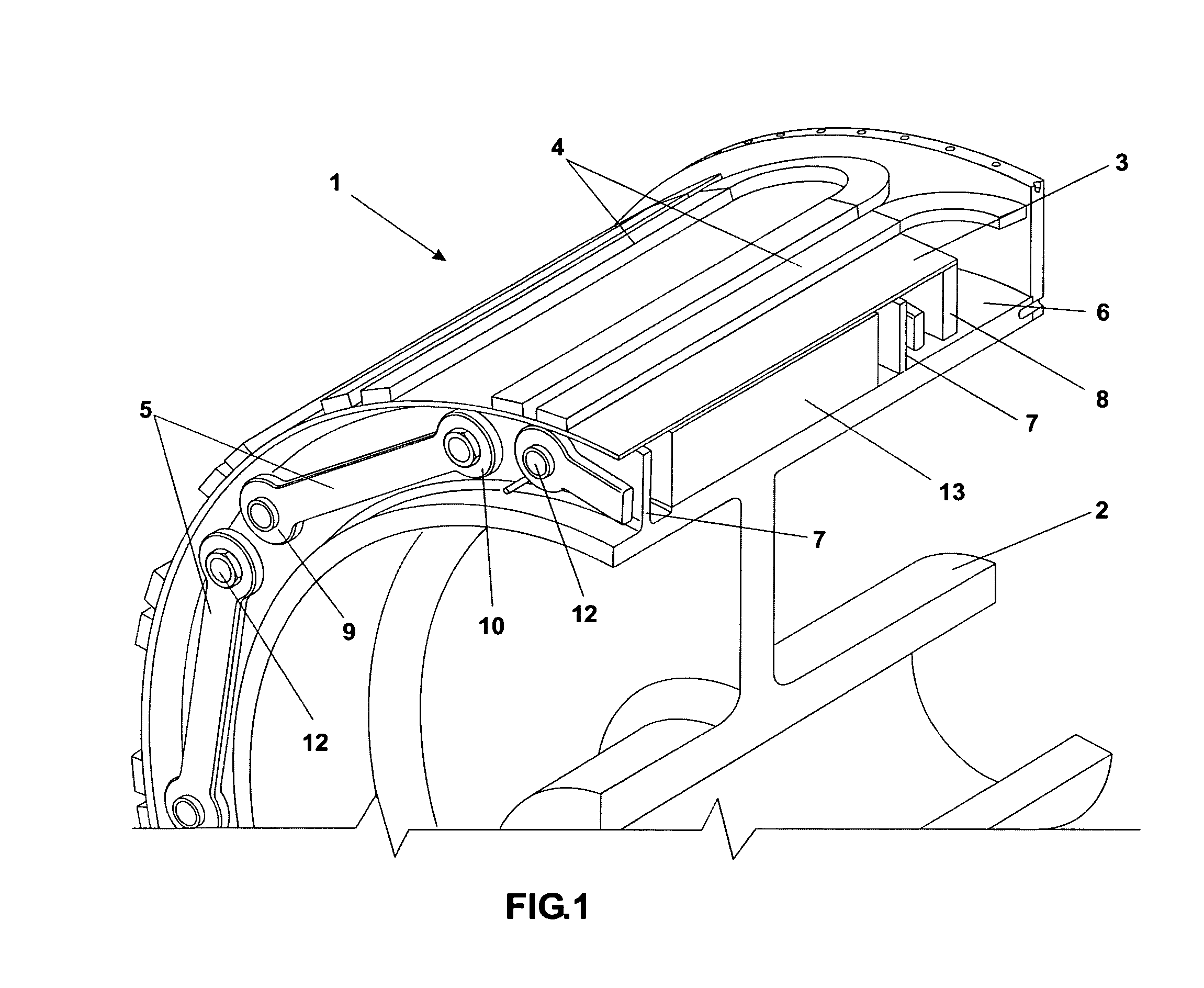
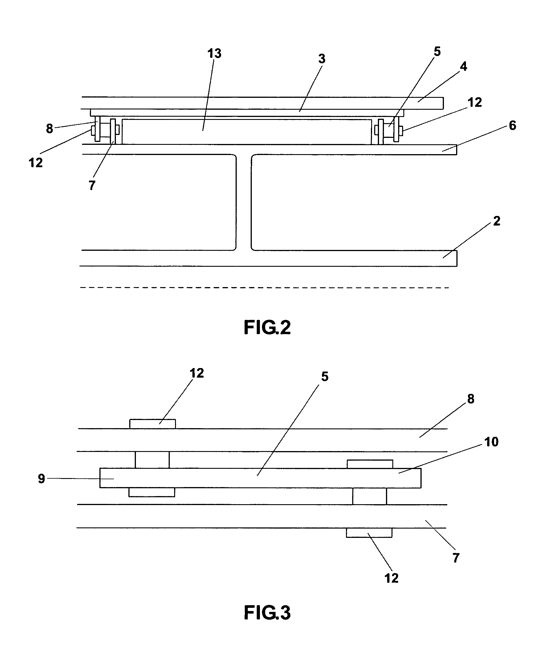
[0041]A cutaway view of a rotor 1 according to the present invention is shown in FIG. 1. The rotor 1 substantially consists of a mounting 2, a field coil support structure 3, a plurality of field coils 4 and a plurality of coupling elements 5. The rotor 1 may form part of an electrical machine (not shown) in a manner that will apparent to a person skilled in the art.

[0042]The mounting 2 is substantially hollow and tubular and has a cylindrical outer surface 6. The mounting 2 forms the central shaft of the electrical machine 1. During operation of the electrical machine, the mounting 2 will be maintained at a substantially ambient operating temperature in order to maintain its necessary physical properties such as strength and torque resistance.

[0043]A pair of circumferentially continuous radially outward extending flanges 7 is formed on the outer cylindrical surface 6 of the mounting 2. Each flange 7 extends radially outward from the mounting 2 a distance that is less than the radia...


PUM


Abstract

A rotor (or a stator) for a superconducting electrical machine includes a mounting that is maintained at substantially ambient temperature during operation of the electrical machine and a field coil support structure. A plurality of superconducting field coils are maintained at cryogenic temperatures during operation of the electrical machine and are supported by the field coil support structure. At least one coupling element is used to fix the field coil support structure to the mounting. The field coil support structure is preferably fixed to the mounting by a plurality of substantially circumferentially extending coupling elements at a first and second axial end of the field coil support structure and the mounting such that the mounting and field coil support structure are substantially separated over their axial lengths by a vacuum gap.

Description

FIELD OF THE INVENTION[0001]The present invention relates to superconducting rotating electrical machines. In particular, the present invention provides a rotor or a stator that is suitable for high temperature superconducting electrical machines. The rotor or stator has high strength and low thermal conduction between the superconducting field coils and the mounting for the field coil support structure.BACKGROUND OF THE INVENTION[0002]Electrical machines typically comprise a cylindrical rotor mounted to rotate around or within a cooperating stator. That is, an electrical machine may have an internal substantially cylindrical rotor mounted within an external stator or an outer cylindrical rotor mounted around an internal stator. In superconducting electrical machines the stator and / or the rotor may include a plurality of superconducting field coils mounted on a field coil support structure, thereby forming a surface that is substantially adjacent to, but spaced apart from, a surface...

Claims


Application Information

Patent Timeline
Patent Type & Authority Patents(United States)
IPC IPC(8): H02K55/04
CPCY02E40/625H02K55/04H02K1/32H02K3/47H02K1/28Y02E40/60H02K55/00
Inventor EUGENE, JOSEPHLE FLEM, GRAHAM DEREK
Owner GE ENERGY POWER CONVERSION TECH
Why Eureka
Try Eureka