
Pendulum mill

a technology of pendulum mill and cylinder head, which is applied in the field of pendulum mill, can solve the problems of increased material stress on the structural parts increased wear on the structural parts, and achieve the effect of reducing the structural height of the pendulum mill

Active Publication Date: 2011-11-17
NEUMAN & ESSER GMBH MAHL UND SICHTSYST
View PDF0 Cites 3 Cited by
  • Summary
  • Abstract
  • Description
  • Claims
  • Application Information

AI Technical Summary

Benefits of technology

[0008]The problem of the invention is to indicate a pendulum mill in which both the noise production and the material stress caused by vibrations are reduced.

Problems solved by technology

It has been found that, when the drive mechanism is fastened to the floor of the building on which the mill housing is also arranged, the drive train forms its own oscillatory system, which generally behaves asynchronously to the oscillatory system of the mill housing and the revolving milling implements located therein, which leads overall to increased material stress for the structural parts of the pendulum mill.
Especially when the two oscillatory systems produce vibrations working in opposite direction, this leads to increased wear on the structural parts.

Method used


Image

  • Pendulum mill
  • Pendulum mill
  • Pendulum mill

Examples


Embodiment Construction

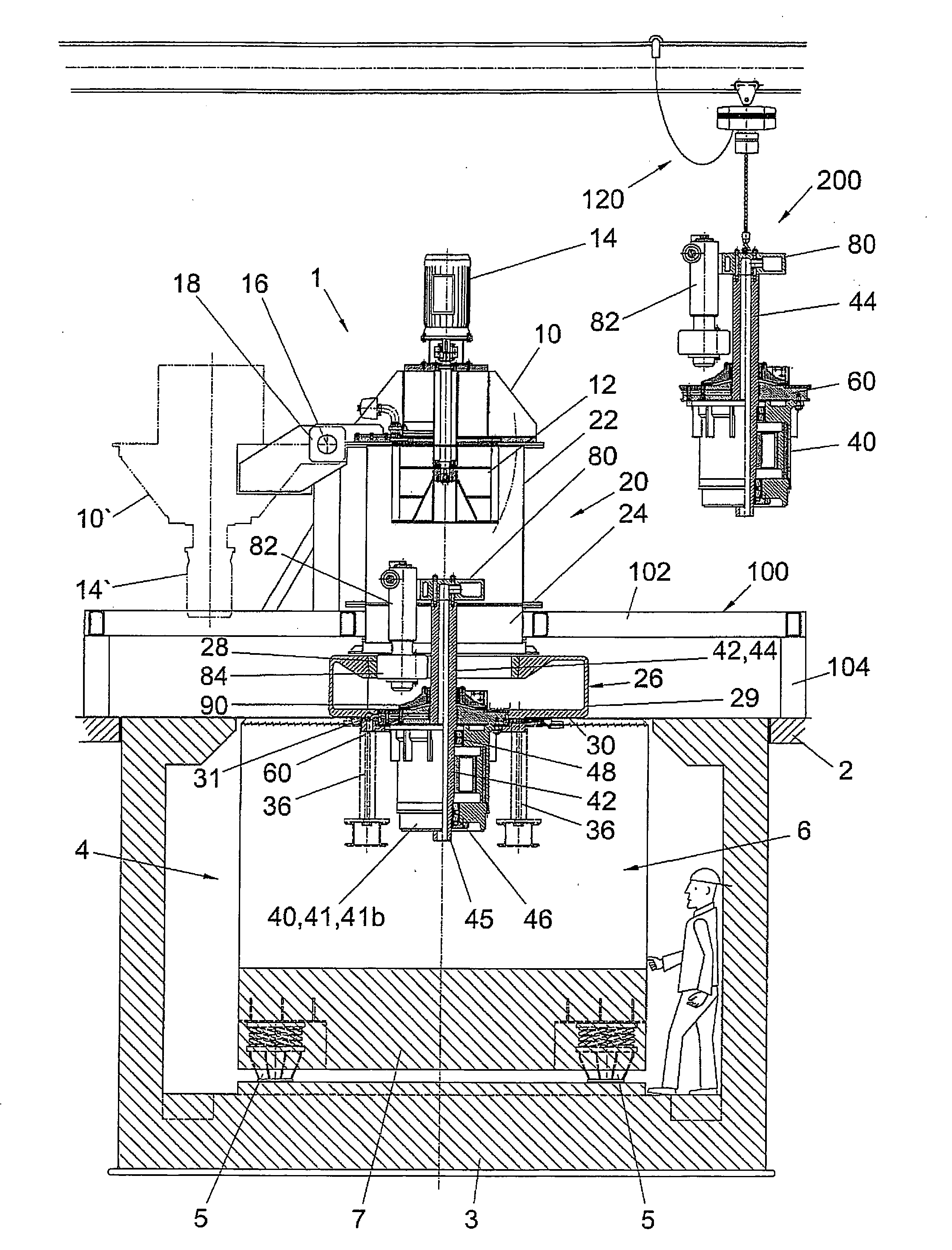
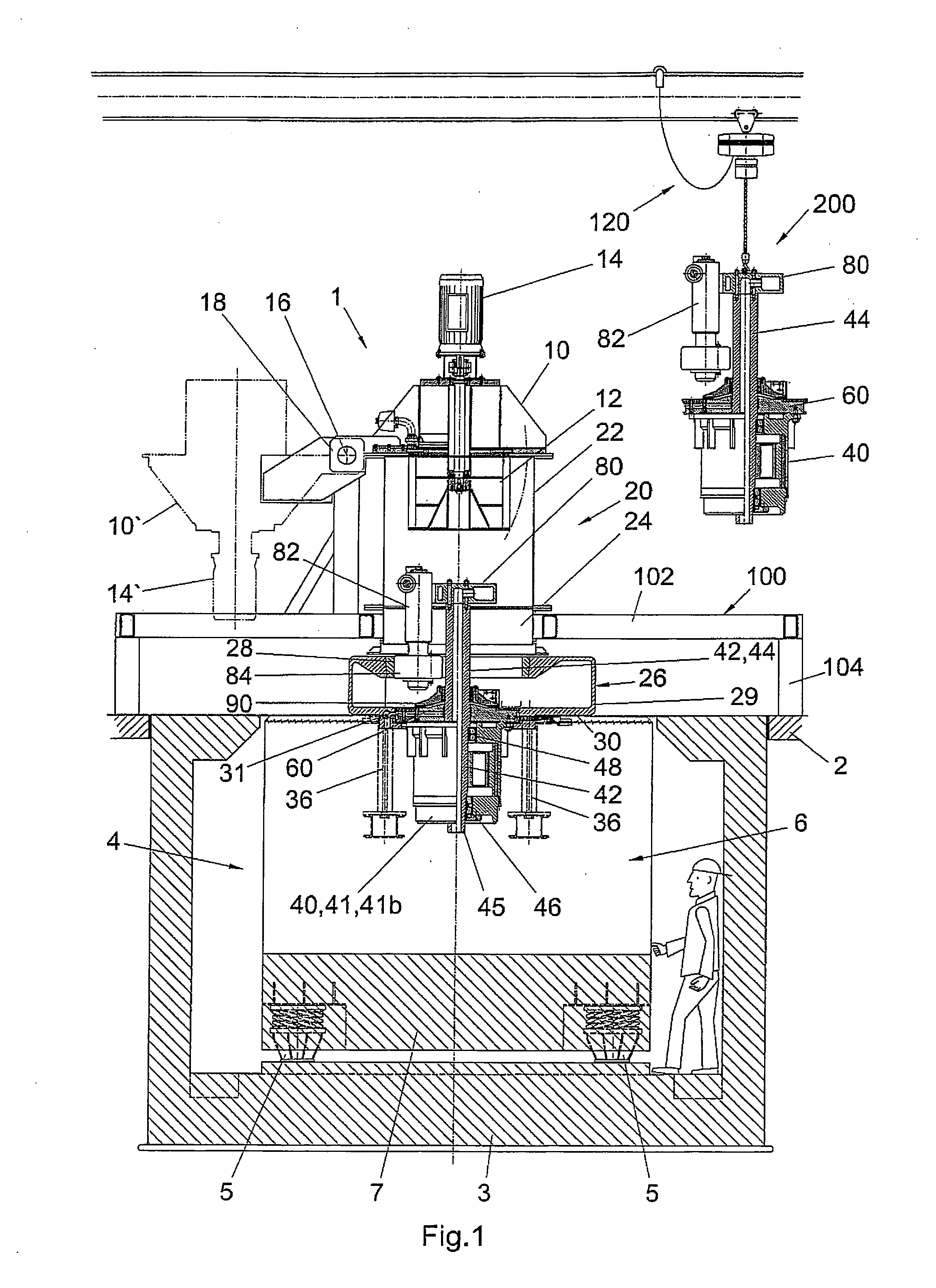
[0040]FIG. 1 shows a pendulum mill 1, having a mill housing 20 consisting of an upper mill housing 22 and a lower mill housing 26, with an intermediate ring 24 arranged between the upper and the lower mill housing. On the upper mill housing 22 is disposed a sifter housing 10, which contains a sifter 12, which protrudes into the inner space of the upper mill housing 22. The sifter 12 is driven by its own sifter drive 14, which is disposed on the sifter housing 10.

[0041]In the mill housing 20 there is vertically disposed a drive shaft 44, having a stationary crosshead 80 at its upper end, from which several milling pendulums 82 are suspended. Only one such milling pendulum 82 can be seen in FIG. 1, having a milling roller 84 at its lower end. The lower mill housing 26 has a grinding track 28 on the inside of its circumferential wall 29, against which the milling rollers 84 are pressed by the centrifugal force when the drive shaft 44 is rotating. The material being milled is comminuted...


PUM


Abstract

A pendulum mill is described that comprises a mill housing, inside which a drive shaft is arranged. Milling pendulums are suspended at the upper end of the drive shaft, while a driving device which is suspended on the bottom wall of the mill housing is disposed at the lower end of the drive shaft.

Description

FIELD OF THE INVENTION[0001]The invention concerns a pendulum mill with a mill housing, in which a drive shaft is disposed, from whose upper end are suspended milling pendulums, and with a drive mechanism connected to the lower end of the drive shaft.BACKGROUND OF THE INVENTION[0002]A pendulum mill is known from DE-PS 33 01 166, having a mill housing, which is connected to the necessary feeding and discharging devices for the material being milled. The mill housing comprises a lower and an upper mill housing, the lower mill housing having an annular grinding track on the inside of its circumferential wall.[0003]In the mill housing there is arranged vertically a driving column, at the upper end of which is secured a stationary crosshead, from which several milling pendulums are suspended to form the milling implements. The milling rollers of the milling pendulums are forced against the grinding track by centrifugal force as the driving column rotates.[0004]At the lower end of the dri...

Claims


Application Information

Patent Timeline
Patent Type & Authority Applications(United States)
IPC IPC(8): B02C15/02
CPCB02C15/02
Inventor SCHWAMBORN, KARL-HEINZVIENKEN, JURGENGALK, JOACHIMPLIHAL, GUNTHERTERIETE, WERNERSIMONS, TONIBIANGA, NORBERT
Owner NEUMAN & ESSER GMBH MAHL UND SICHTSYST
Learn More