High Dynamic Range Displays Using Filterless LCD(s) For Increasing Contrast And Resolution

a high dynamic range and display technology, applied in the field of high dynamic range displays, can solve the problems of hdr displays that cannot reproduce starfields and other challenging images, and achieve the effects of improving black levels, high dynamic range, and increasing contrast ratio

Active Publication Date: 2011-11-17
DOLBY LAB LICENSING CORP
View PDF12 Cites 172 Cited by
  • Summary
  • Abstract
  • Description
  • Claims
  • Application Information

AI Technical Summary

Benefits of technology

In one embodiment, the present invention provides a high dynamic range display comprising a color LCD panel for generating an image (the image-generating panel) and an LCD panel without color filters (the contrast-improving panel) arranged to increase the contrast ratio and improve black levels (either making them darker or increasing the color and brightness fidelity of dark areas that are not intended to be completely black) in the generated image.

Problems solved by technology

However, commercially available HDR displays have deficiencies in reproducing starfields and other challenging images mainly due to parallax, backlight leakage, and other issues, and artifacts resulting therefrom.

Method used


Image

  • High Dynamic Range Displays Using Filterless LCD(s) For Increasing Contrast And Resolution
  • High Dynamic Range Displays Using Filterless LCD(s) For Increasing Contrast And Resolution
  • High Dynamic Range Displays Using Filterless LCD(s) For Increasing Contrast And Resolution

Examples


Embodiment Construction

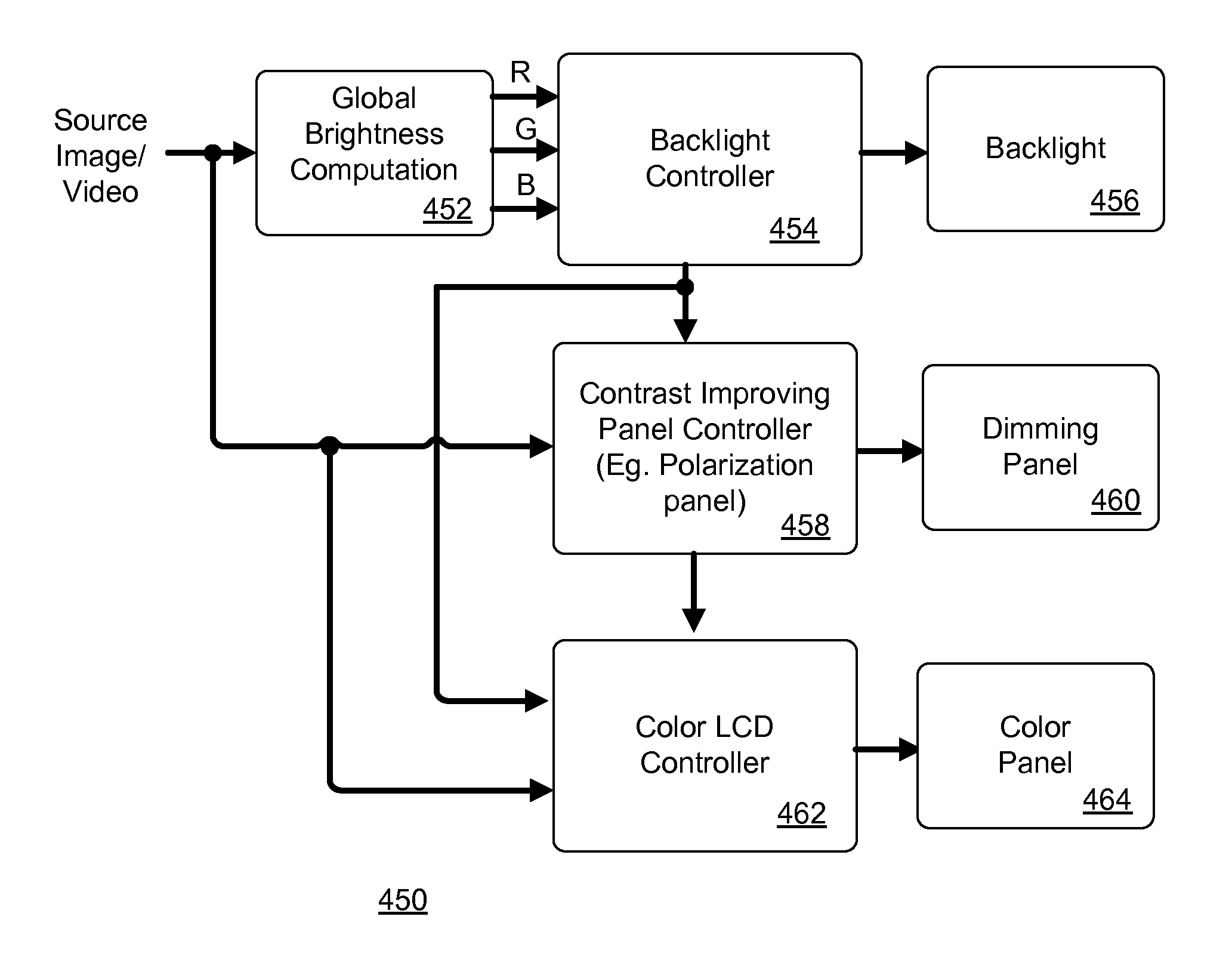
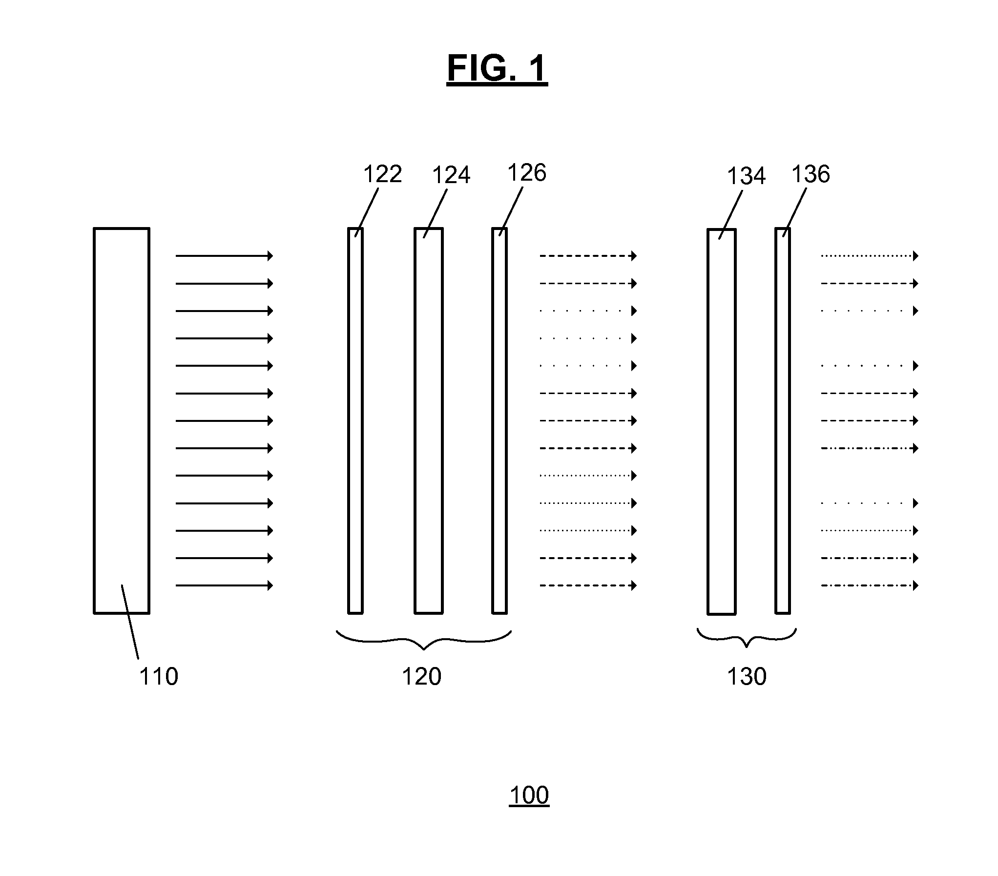
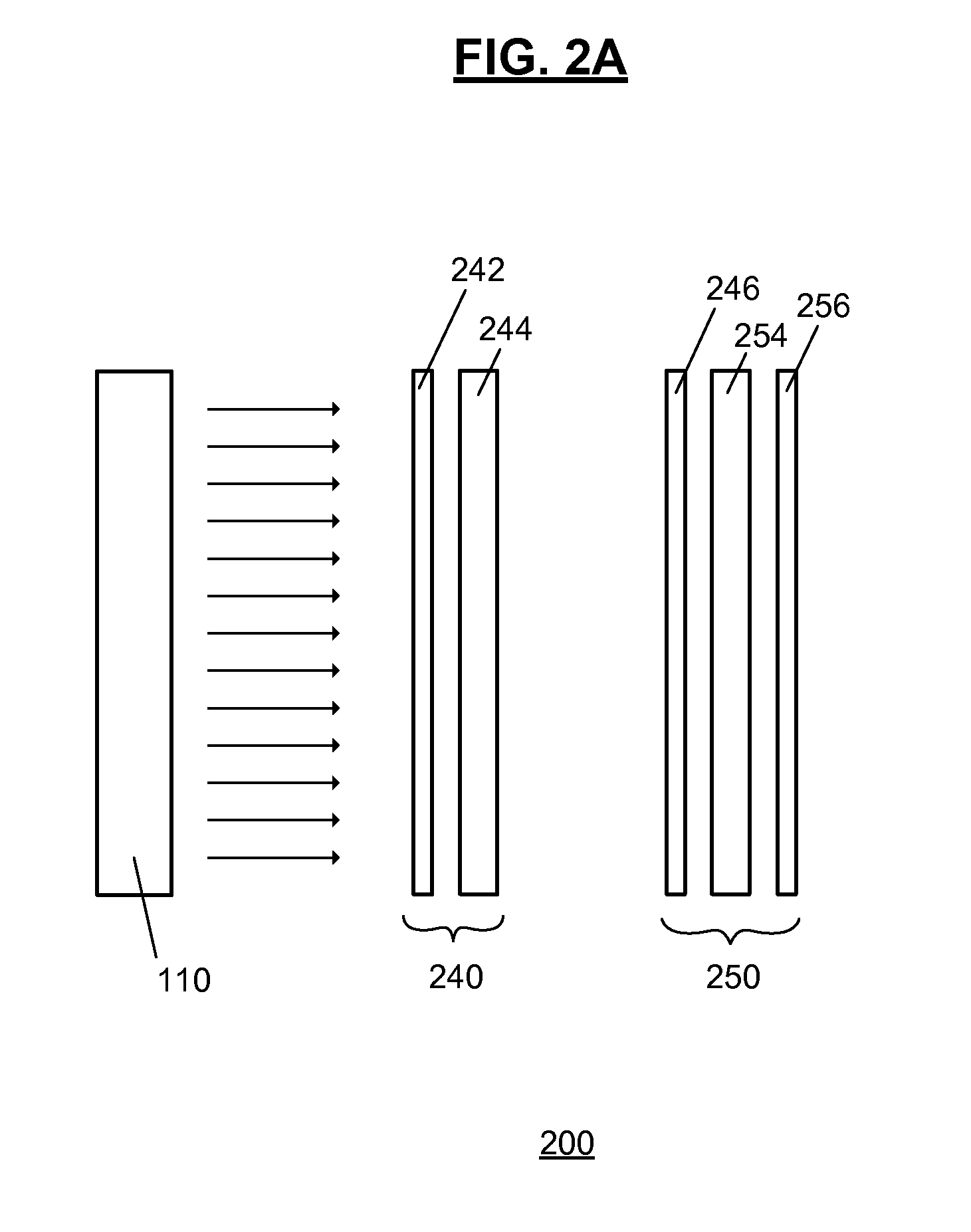
Referring now to the drawings, wherein like reference numerals designate identical or corresponding parts, and more particularly to FIG. 1 thereof, there is illustrated a new construction for a high dynamic range display 100 according to an embodiment of the present invention. The display 100 includes a backlight 110 which may be a standard CCFL or other broadband lighting source (e.g., LEDs, OLEDs, etc.). In addition, the backlight may be direct lit (light source(s) directly illuminating downstream modulation panels) or edge lit (as is popular in many thin screen LCD display designs). Further yet, the backlight may be constant, globally dimmed, or locally dimmed. The light source for this display can be white, controllable luminance, or multiple color driven.

The backlight 110 illuminates downstream modulators, including, in this example, an LCD panel 120 which modulates the backlight in intensity and color. A controllable polarizer (or contrast-improving panel) 130 further modulate...


PUM

PropertyMeasurementUnit
frequencyaaaaaaaaaa
coloraaaaaaaaaa
brightnessaaaaaaaaaa

Abstract

A display provides increased contrast and resolution via first LCD panel energized to generate an image and a second LCD panel configured to increase contrast of the image. The second panel is an LCD panel without color filters and is configured to increase contrast by decreasing black levels of dark portions of images (making them blacker or darker) using polarization rotation and filtration. Preferably, the second LCD panel is of higher resolution than the first LCD panel. The panels may be directly illuminated or edge lit, and may be globally or locally dimmed monochrome or multi primary lights that may also include individual control of color intensities for each image or frame displayed. The panels may be placed in any order, but preferably are arranged such that active layers in each panel are as close together as possible. Brightness is maintained by the combination of reusing polarization between the panels and by not going through more than one set of color filters. Improved contrast is a result of using multiple light modulators in series.

Description

COPYRIGHT NOTICEA portion of the disclosure of this patent document contains material which is subject to copyright protection. The copyright owner has no objection to the facsimile reproduction by anyone of the patent document or the patent disclosure, as it appears in the Patent and Trademark Office patent file or records, but otherwise reserves all copyright rights whatsoever.BACKGROUND OF THE INVENTION1. Field of InventionThe present invention relates to High Dynamic Range Displays (HDR), and more particularly to HDR displays using dual modulation.2. Discussion of BackgroundHigh Dynamic Range (HDR) displays are generally defined as having a dynamic range of greater than 800 to 1. Recent advances in technology have produced displays claiming contrast ratios of more than 1,000,000 to 1.Generally speaking, these higher contrast ratio HDR displays utilize local dimming of the backlight that illuminates the LCD panel. An early patent in this area, U.S. Pat. No. 6,891,672, by Whitehea...

Claims


Application Information

Patent Timeline
Patent Type & Authority Applications(United States)
IPC IPC(8): G02F1/1335G09G5/10G09G5/02G09G3/36G09G5/00
CPCG02F1/133606G02F2001/133601G09G3/3426G09G2300/023H04N13/0447G09G2360/16G02F1/13471H04N13/0422H04N13/0434G09G2320/0646G02F1/133601H04N13/324H04N13/337H04N13/351G02F1/133G02F1/1335G09G3/36G09G5/00
Inventor ERINJIPPURATH, GOPALGILBERT, JOHN
Owner DOLBY LAB LICENSING CORP
Why Eureka
Try Eureka