3-phase high-power ups

a high-power up and three-phase technology, applied in the direction of dc source parallel operation, conversion with intermediate conversion to dc, emergency power supply arrangement, etc., can solve the problems of lowering efficiency, increasing conduction and switching losses, etc., to achieve the effect of reducing the physical size of the 3-phase up, reducing the switching loss, and increasing efficiency

Active Publication Date: 2011-11-17
AMERICA POWER CONVERSION CORP
View PDF0 Cites 30 Cited by
  • Summary
  • Abstract
  • Description
  • Claims
  • Application Information

AI Technical Summary

Benefits of technology

[0018]Various aspects of the invention may provide one or more of the following capabilities. Reliable 3-phase power can be provided to a load. Physical size of a 3-phase UPS can be reduced compared to prior techniques. Efficiency can be increased compared with prior techniques. A transformerless circuit can be used to convert AC power to DC, DC power to AC, and DC power from a first voltage to a second voltage. IGBT switching losses can be reduced compared to prior techniques. Components having a lower voltage rating can be used when compared with prior techniques. Heat losses can be reduced compared with prior techniques. The desire for flying capacitors and / or clamp diodes can be reduced, when compared with prior techniques. A voltage of a battery used with a UPS can be reduced compared to prior techniques. Unbalanced operation caused by a mismatch of the voltage provided to the input of a 3-phase UPS and the power drawn from the output of the 3-phase UPS can be compensated without using a transformer.

Problems solved by technology

The use of 1200 V components, however, typically leads to increased conduction and switching losses, thus lowering the efficiency.

Method used


Image

  • 3-phase high-power ups
  • 3-phase high-power ups
  • 3-phase high-power ups

Examples


Embodiment Construction

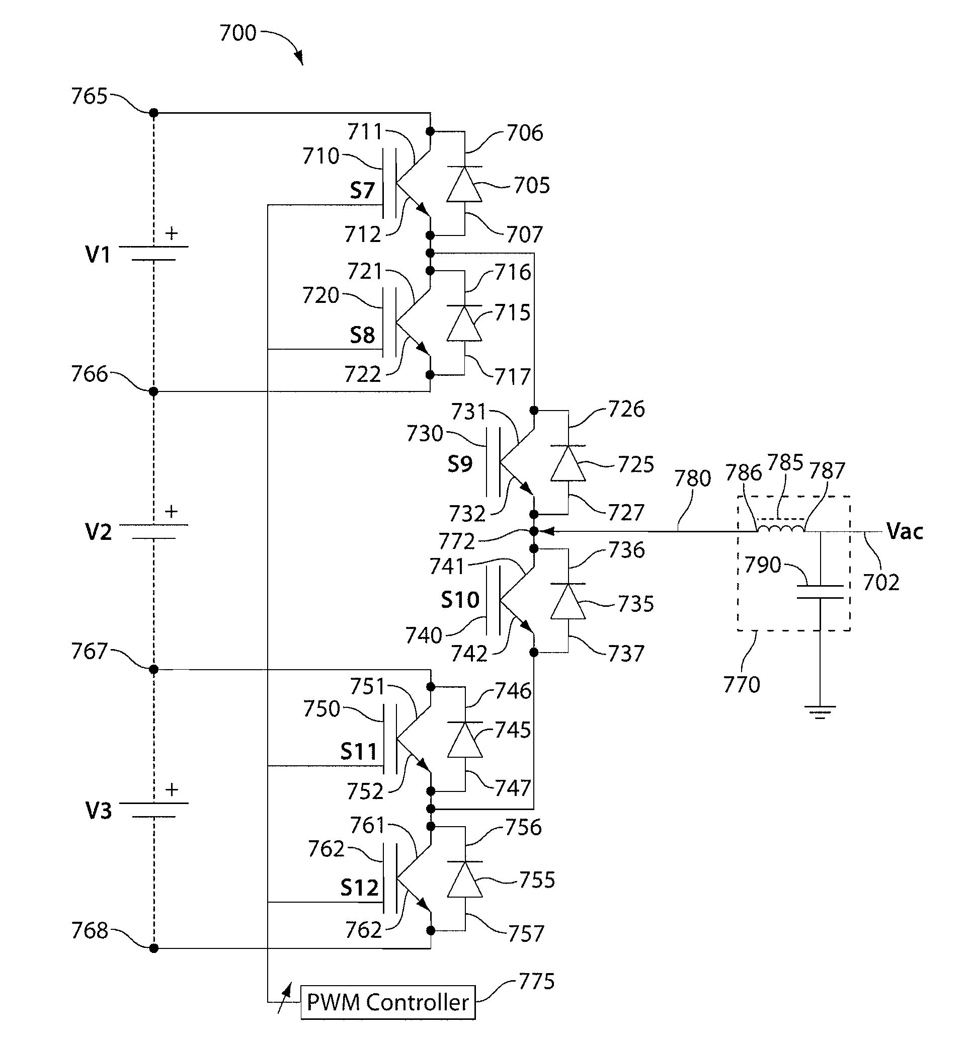
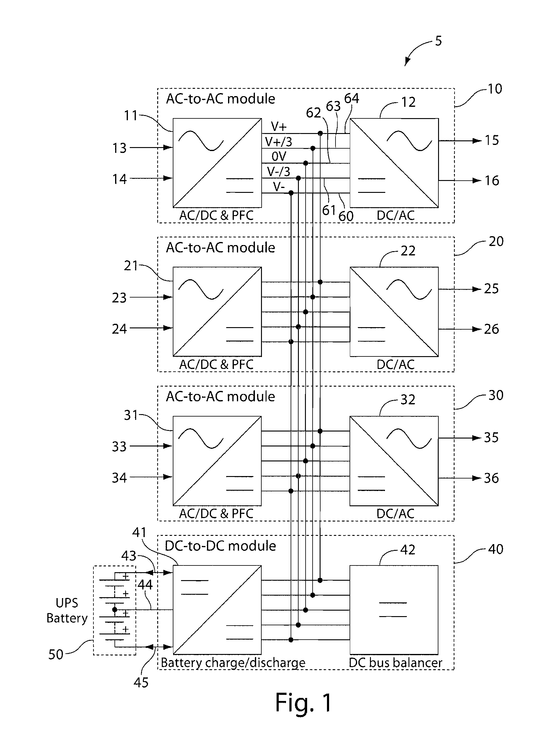
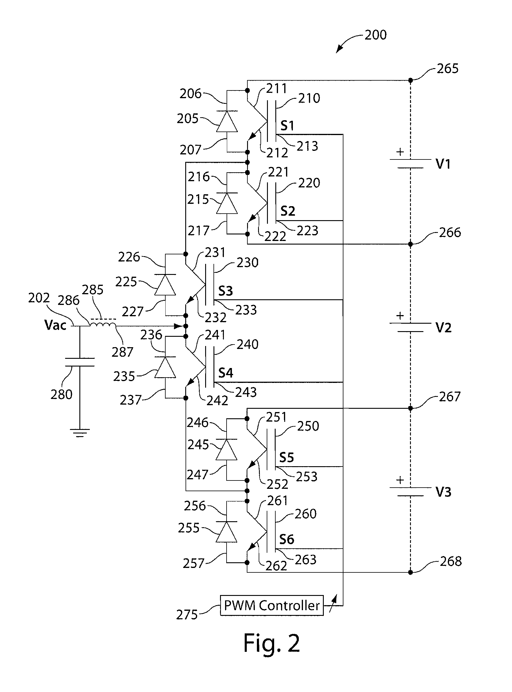
[0034]Embodiments of the invention provide techniques for providing an uninterruptible 3-phase power supply to a load. For example, a transformerless 3-phase uninterruptible power supply includes AC / DC converters (e.g., power factor correction modules), DC / AC converters (e.g., inverters), a DC / DC conversion module, multiple DC buses, and a DC bus balancer. The AC / DC converters receive 3-phase AC power (e.g., 3×400 V or 3×480 V phase-phase) from a 3-phase power source and convert the 3-phase power into DC power (e.g., with multiple voltage levels). Each of the AC / DC converters receives one phase of the 3-phase power connection. Under normal operation (e.g., when suitable 3-phase power is received from the 3-phase power source), the DC power present on the DC buses provides power to the DC / AC converters. Furthermore, during normal operation, a DC / DC converter converts the DC power present on the DC buses to a voltage used to charge the battery. During other times (e.g., when the 3-pha...


PUM


Abstract

A 3-phase uninterruptible power supply (UPS) including first, second, and third AC / DC converters, a DC / DC converter, and at least one DC / AC converter coupled to multiple electrical buses. The first, second, and third AC / DC converters each being configured to receive AC power and to provide multiple DC signals to the multiple electrical buses. The DC / DC converter being configured to convert DC voltages present on the multiple electrical buses to a DC voltage that can be used to charge a battery. The DC / AC converter being configured to receive DC power from the multiple electrical buses and to provide an AC output. The 3-phase UPS being configured such that when suitable AC power is provided to the AC / DC converters, the DC / DC converter is configured to charge a battery, and when suitable AC power is not provided to the AC / DC converters, the DC / DC converter is configured to provide DC power to the multiple electrical buses using power provided by the battery.

Description

BACKGROUND OF INVENTION[0001]Uninterruptible power supplies (UPSs) including voltage converters are fundamental parts of many electrical systems such as power supply systems for computers and servers in data centers. UPSs can be used with many typical power systems including single and 3-phase connections, and can be used with low-power systems (e.g., a household computer) and high-power systems (e.g., large data centers or process facilities). High-power systems typically use a 3-phase power connection (e.g., X, Y, and Z phases). A 3-phase UPS voltage converter is typically used to provide 3-phase AC power to a 3-phase load, to convert a 3-phase AC voltage from one level to another, and to provide 3-phase power to a load in the event of a power failure. The input and output connections to a 3-phase UPS voltage converter are typically three- or four-terminal connections, one connection for each phase of the 3-phase power connection and an optional neutral connection. A battery is al...

Claims


Application Information

Patent Timeline
Patent Type & Authority Applications(United States)
IPC IPC(8): H02M7/53862
CPCH02J1/102H02J9/062H02J7/345H02M5/40H02J7/0014H02M7/487H02M3/158
Inventor NIELSEN, HENNING ROAR
Owner AMERICA POWER CONVERSION CORP
Why Eureka
Try Eureka