Solid state lighting system and a driver integrated circuit for driving light emitting semiconductor devices

a semiconductor device and integrated circuit technology, applied in the direction of electric variable regulation, process and machine control, instruments, etc., can solve the problems of substantial power loss and heat conversion, and achieve the effect of lower voltage rating and higher switching frequency

Active Publication Date: 2013-02-12
NXP BV
View PDF10 Cites 14 Cited by
  • Summary
  • Abstract
  • Description
  • Claims
  • Application Information

AI Technical Summary

Benefits of technology

[0008]It is an object of the present invention to provide a solid state lighting system that uses drivers with lower voltage ratings that are cheaper and also allow for higher switching frequencies to be used.
[0011]Accordingly, such a solid state system serves to overcome the drawbacks of the typical architectures of circuits for driving the string of one or more light emitting diodes or devices based on only a single voltage supply. The potentials provided by the two power supplies may have a positive or negative sign and any potential in the system may be defined as ground. If more than a single voltage supply is used for an LED, or a string of LEDs coupled in series, undesired power losses can be avoided. Further, the requirements for the electronic components may be reduced, if the voltage drop across the components, i.e. the driver's circuit, becomes smaller. Therefore, the driver can be designed to operate at a reduced voltage, which can be much lower than the voltages across the LEDs. This is advantageous as more than one LED can be driven by the driver.
[0012]Accordingly, by coupling a second supply voltage (in addition to a first supply voltage) to the driver circuit, the voltage across the driver circuit is reduced. The voltages across the driving circuit and the light emitting device can thus be adjusted in a more appropriate manner than by single supply solutions. The additional degree of freedom provided by the second power supply, allows a lower breakdown voltage rating for the power devices. The first supply voltage may be controlled to a minimum, which is determined by voltages required by the string of one or more light emitting devices having the highest forward voltage. If variations of the forward voltages of each LED of a string occur which may be a consequence of temperature, aging or production spread, the present invention is further capable of adjusting the voltages across the LEDs appropriately in order to compensate the negative effects. Substantial losses of power produced by heat in the electronic components may be avoided, if the voltages across the driving means are adjusted to be not greater than necessary.

Problems solved by technology

If the voltage across the driving means is greater than necessary, a substantial loss of power occurs which is turned into heat.
A second undesired effect of high voltages in the current sources or sinks resides in the need for components being suitable to withstand high voltages, temperatures or the like, which are a consequence of improperly adjusted voltages across the components.

Method used


Image

  • Solid state lighting system and a driver integrated circuit for driving light emitting semiconductor devices
  • Solid state lighting system and a driver integrated circuit for driving light emitting semiconductor devices
  • Solid state lighting system and a driver integrated circuit for driving light emitting semiconductor devices

Examples


first embodiment

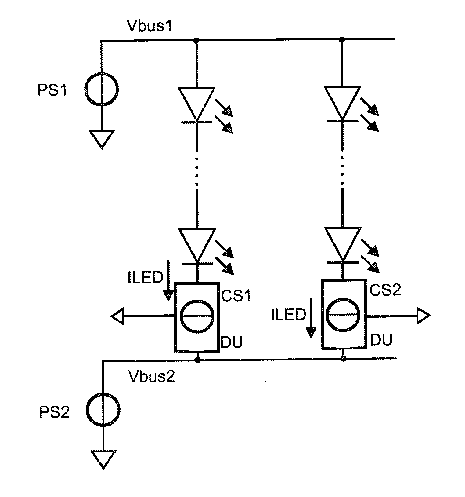
[0037]FIG. 5 shows a simplified block diagram of an electronic system, in particular a solid state lighting system, according to the present invention. The solid state lighting system comprises a first and second power supply PS1, PS2 for providing a first and second supply voltage Vbus1, Vbus2. The block LEDdr may have a third terminal involved with the power distribution, here indicated as ground, that carries the current ILED during part of the time. The lighting system furthermore comprises a string of light emitting diodes LEDstr and a driver circuit LEDdr for driving the string of LEDs. Accordingly, the first and second power supplies PS1, PS2 are coupled to the string of light emitting diodes LEDstr. The two power supplies PS1, PS2 provide two potential Vbus1 and Vbus2, and they may be of any type, linear, inductive, or capacitive switch mode, battery, solar cell, fuel cell, etc., or, they even may share parts in common with the LEDdr circuitry. If the power supplies and the ...

second embodiment

[0038]FIG. 6 shows a simplified schematic of the invention. A power supply PS is provided which is used to obtain a first supply voltage Vbus1. A plurality of strings of LEDs is coupled to the first supply voltage Vbus1. In series with each string of LEDs, an inductor L and a switch T (which can be implemented as a transistor) is provided. In addition to the first supply voltage Vbus1, a second supply voltage Vbus2 is provided. A diode D is coupled between the inductor and the second supply voltage Vbus2.

[0039]It should be noted that each driving unit or each string of LEDs comprises an associated transistor T, inductor L and a fly-back diode D. Thus, the driver unit constitutes a three terminal unit. As an illustrative example, the voltage of the first supply voltage Vbus1 corresponds to 300V and the voltage across the strings of LEDs corresponds to VLED chain=173V−237V. Therefore, the second supply voltage Vbus2 must be >127V, as the difference between the first and second supply ...

third embodiment

[0042]According to the second and third embodiment, a driving unit with three supply terminals can be provided in which all three currents from the LED are flowing.


PUM


Abstract

The present invention relates to a solid state lighting system comprising at least one light emitting semiconductor device, at least one driver for driving a predetermined current through the at least one light emitting semiconductor device. The lighting system furthermore comprises a first voltage supplying unit coupled to provide a first supply voltage to a first side of the at least one light emitting semiconductor device, and a second voltage supplying unit coupled to provide a second supply voltage for the at least one light emitting semiconductor device. The first and the second supply voltages are selected to optimize the voltage drop across the at least one light emitting semiconductor device.

Description

FIELD OF THE INVENTION[0001]The present invention relates to a solid state lighting system and a driver-integrated circuit for driving light emitting semiconductor devices.BACKGROUND OF THE INVENTION[0002]Light emitting semiconductor devices play an important role in today's lighting systems. Applications for light emitting semiconductor devices, such as light emitting diodes (LEDs) include general illumination, automotive and consumer applications. Today's technologies provide a wall-plug power efficiency of about 15%-20%, which is projected to increase up to 30% and more. Cold cathode fluorescent lamps (CCFL) being generally used in liquid crystal display (LCD) backlighting applications for notebooks, monitors, or television provide a power efficiency of about 15%. A power efficiency of about 30% pushes light emitting diodes on the same level as high frequency tubular lamps (HF-TL) being used for general illumination applications (e.g. home, office, factory, etc.).[0003]FIG. 1 sho...

Claims


Application Information

Patent Timeline
Patent Type & Authority Patents(United States)
IPC IPC(8): H05B37/00H05B44/00
CPCG09G3/342H05B33/0815H05B33/0818H05B33/0827G09G2330/021H05B45/46H05B45/385H05B45/375H05B45/38
Inventor HOOGZAAD, GIANSCHOOFS, FRANCISCUS A. C. M.
Owner NXP BV
Why Eureka
Try Eureka