Diagnostic method for electric propulsion system with reconfigurable battery system

Active Publication Date: 2021-03-25
GM GLOBAL TECH OPERATIONS LLC
View PDF1 Cites 0 Cited by
  • Summary
  • Abstract
  • Description
  • Claims
  • Application Information

AI Technical Summary

Benefits of technology

[0004]Described herein are an electric propulsion system for a mobile platform and a method for diagnosing electrical conditions of the electric propulsion system. The electric propulsion system includes a battery system, a traction power inverter module (“TPIM”), and an electric machine. The battery system, which is connected to positive and negative voltage bus rails, has multip...

Problems solved by technology

Additionally, the possible electrical fault conditions ma...

Method used


Image

  • Diagnostic method for electric propulsion system with reconfigurable battery system
  • Diagnostic method for electric propulsion system with reconfigurable battery system
  • Diagnostic method for electric propulsion system with reconfigurable battery system

Examples


Embodiment Construction

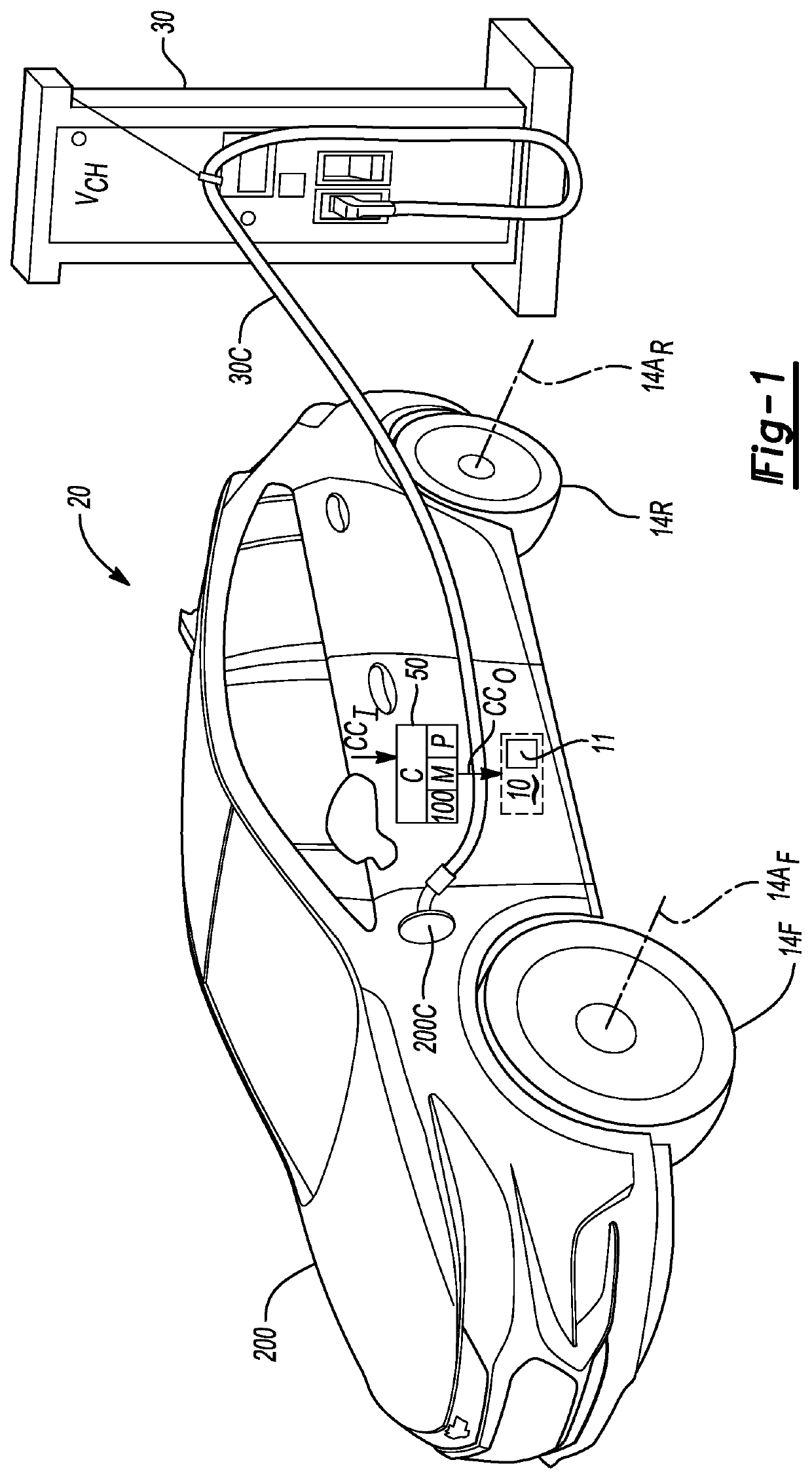
[0023]Referring to the drawings, wherein like reference numbers refer to the same or like components in the several Figures, a mobile platform 20 is depicted in FIG. 1 that includes a body 200 and an electric propulsion system 10, with the electric propulsion system 10 including a battery system 11. In the depicted representative embodiment, the electric propulsion system 10 powers propulsion functions of the mobile platform 20, with “exemplary” as used herein meaning a non-limiting example configuration illustrating certain aspects of the present teachings, i.e., not necessarily advantageous or preferred over other possible implementations. The mobile platform 20 is shown undergoing a direct current fast-charging (“DCFC”) operation in which the battery system 11 is electrically connected to an off-board DCFC station 30, e.g., via a vehicle charging port 200C that is internally connected to a DC charge coupler (not shown) using a length of high-voltage charging cable 30C. Although n...


PUM


Abstract

An electric propulsion system for a mobile platform includes a battery system connected to positive and negative bus rails, an accessory load having a rotary electric machine, a traction power inverter module (“TPIM”), and an accessory load, switches configured to transition the battery modules to a series-connected (“S-connected”) configuration during a direct current fast-charging (“DCFC”) operation of the battery system, and a controller. When battery modules of the battery system are connected in series during a direct current fast-charging (“DCFC”) operation, the controller executes a diagnostic method to determine bus rail voltages on the positive and negative bus rails and a mid-bus voltage, identifies a diagnosed electrical condition of the electric propulsion system by comparing the voltages to expected values or ranges, and executes a control action in response to the diagnosed electrical condition.

Description

INTRODUCTION[0001]The present disclosure relates to a diagnostic method for use with an electric powertrain configured for energizing propulsion functions aboard a vehicle or other rechargeable mobile platform. Electric powertrains often include at least one polyphase / alternating current (“AC”) rotary electric machine constructed from a wound stator and a magnetic rotor. The stator windings are connected to an AC-side of a power inverter, with a direct current (“DC”)-side of the power inverter in turn connected to a DC voltage bus. When the electric machine functions as a traction motor, switching control of the ON / OFF states of individual semiconductor switches of the power inverter generates an AC output voltage at a level suitable for energizing the stator windings. The sequentially-energized stator windings produce a rotating magnetic field, which ultimately interacts with a rotor field to produce machine rotation and motor output torque.[0002]The above-noted DC voltage bus is e...

Claims


Application Information

Patent Timeline
IPC IPC(8): H02J7/00B60L15/00B60L50/60
CPCH02J7/0024B60L50/66B60L15/007H02J7/0021G01R31/343H02J2310/48H02J1/082Y02T10/70B60L3/0061B60L53/11B60L58/19B60L2240/547Y02T10/7072Y02T90/14
Inventor LI, SHIFANGIVAN, WILLIAM T.CONLON, BRENDAN M.FAN, YUE
Owner GM GLOBAL TECH OPERATIONS LLC
Why Eureka
Try Eureka