Interleaved flyback converter device with leakage energy recycling

a converter device and leakage energy technology, applied in the direction of electric variable regulation, process and machine control, instruments, etc., can solve the problems of unfavorable mass production in industry, high manufacturing cost, complicated control thereof, etc., and achieve low voltage rating, increase efficiency, and reduce the effect of withstand voltag

Active Publication Date: 2013-02-12
NAT CHENG KUNG UNIV
View PDF10 Cites 6 Cited by
  • Summary
  • Abstract
  • Description
  • Claims
  • Application Information

AI Technical Summary

Benefits of technology

[0008]The object of the present invention is to provide an interleaved flyback converter device, which can recycle leakage energy efficiently and have the advantages of low cost and high efficiency.
[0010]The present invention uses divided voltage of the capacitors as input voltage, so that the two flyback converters can have lower voltage rating. In addition to recycling leakage inductance energy for increasing efficiency, the two flyback converters with lower withstand-voltage in the present invention are provided with lower switching loss.

Problems solved by technology

; however, the control thereof is complicated With reference to FIG. 2, there is shown another flyback converter in prior art.
However, it has disadvantage of high-cost manufacturing, and thus is unfavorable to mass production in industry.
However, this circuit layout is complicated, resulting in a disadvantage of high cost.

Method used


Image

  • Interleaved flyback converter device with leakage energy recycling
  • Interleaved flyback converter device with leakage energy recycling
  • Interleaved flyback converter device with leakage energy recycling

Examples


Embodiment Construction

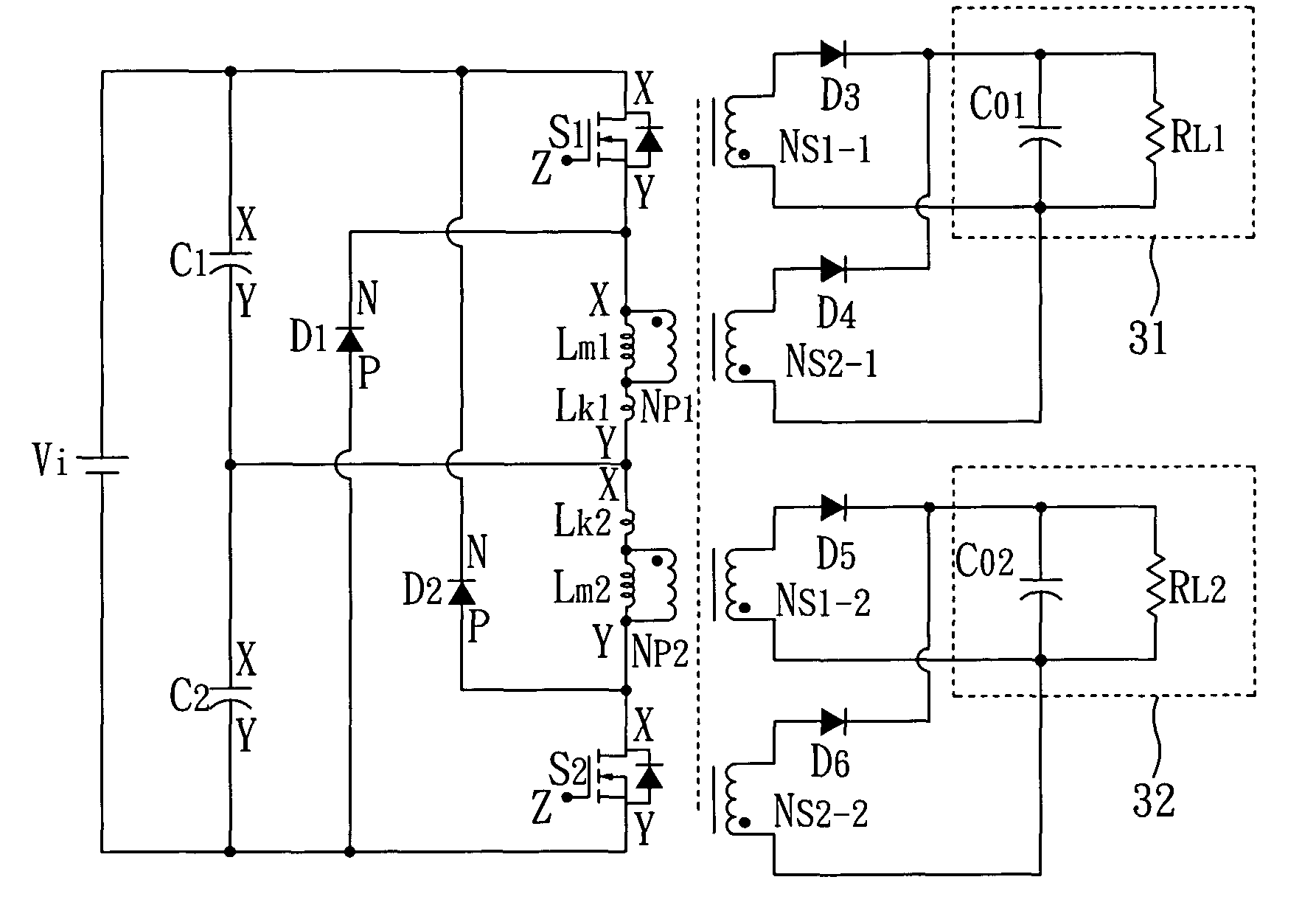
[0018]With reference to FIG. 4, there is shown a first circuit layout with signal output voltage of the interleaved flyback converter device in accordance with one embodiment of the present invention. As shown, the interleaved flyback converter device with leakage energy recycling includes: a first flyback converter 1, a second flyback converter 2, and an input power Vi. The first flyback converter 1 and the second flyback converter 2 are connected in parallel to a load 3 (Co, RL).

[0019]The first flyback converter 1 includes a first capacitor C1, a first switch S1, a first diode D1, a first transformer T1 and a third diode D3. The second flyback converter 2 includes a second capacitor C2, a second switch S2, a second diode D2, a second transformer T2 and a fourth diode D4. The input power Vi is connected to the first capacitor C1 of the first flyback converter 1, and the second capacitor C2 of the second flyback converter 2.

[0020]The first transformer T1 has a primary winding Np1 an...


PUM


Abstract

An interleaved flyback converter device with leakage energy recycling includes: two flyback converters and an input power. Each flyback converter includes a capacitor, a switch, two diodes, and a transformer. The input power is connected to the capacitors of the two flyback converters respectively. By using the capacitors as input voltage, the two flyback converters are provided with lower voltage rating. The diodes are used to recycle leakage energy directly, and to clamp voltage on power components. Therefore, in addition to enhancing efficiency via recycling leakage energy, the two flyback converters have lower switching losses due to lower switching voltage.

Description

CROSS REFERENCE TO RELATED APPLICATION[0001]This application claims the benefits of the Taiwan Patent Application Serial Number 099138111, filed on Nov. 5, 2010, the subject matter of which is incorporated herein by reference.BACKGROUND OF THE INVENTION[0002]1. Field of the Invention[0003]The invention relates generally to an interleaved flyback converter device and, more particularly, to an interleaved flyback converter device with leakage energy recycling.[0004]2. Description of Related Art[0005]Generally, transformers are used for electrical isolation and voltage level adjustment. A flyback converter also has characteristic of electrical isolation, but its magnetic components are not mainly used for voltage level adjustment. Instead, the flyback converter makes use of coupled inductors to achieve the property of energy conversion. Therefore, it is particularly useful for energy storage and energy release. In addition to the features of low-cost and simple circuit layout, the flyb...

Claims


Application Information

Patent Timeline
Patent Type & Authority Patents(United States)
IPC IPC(8): H02M3/335H02M7/00
CPCH02M3/285H02M3/33569H02M2001/009H02M2001/0074H02M1/0074H02M1/009H02M3/01
Inventor LIANG, TSORNG-JUUHUANG, WEN-YUYANG, LUNG-SHENGCHEN, SHIH-MINGCHEN, JIANN-FUH
Owner NAT CHENG KUNG UNIV
Why Eureka
Try Eureka