DC-to-DC converter and electric motor drive system using the same

a technology of dc-to-dc converter and electric motor, which is applied in the direction of process and machine control, ignition automatic control, instruments, etc., can solve the problems of increased manufacturing cost of controllers, uneven voltage sharing between capacitors, etc., and achieves less susceptible to parameter variation, lower voltage ratings, and reduced manufacturing costs

Active Publication Date: 2009-10-20
FORD GLOBAL TECH LLC
View PDF35 Cites 5 Cited by
  • Summary
  • Abstract
  • Description
  • Claims
  • Application Information

AI Technical Summary

Benefits of technology

[0008]Accordingly, it may be desirable to have a DC-to-DC converter, configurable for use with high DC voltages, wherein the DC-to-DC converter may be implemented with capacitors having lower voltage ratings and / or may be less susceptible to parameter variation, as compared to conventional converters such as 10 and 20. Such a converter may decrease the cost of manufacturing by reducing the need for closely matched capacitors and / or the need for capacitors at higher voltage ratings.

Problems solved by technology

It is known, however, that parameter variations, such as unmatched capacitances, leakage resistance and the like, between the plurality of capacitors 22 may result in uneven voltage sharing between the capacitors 22.
The use of such closely matched or higher voltage rated capacitors generally results in an increased cost of manufacturing the controller 20.

Method used


Image

  • DC-to-DC converter and electric motor drive system using the same
  • DC-to-DC converter and electric motor drive system using the same
  • DC-to-DC converter and electric motor drive system using the same

Examples


Embodiment Construction

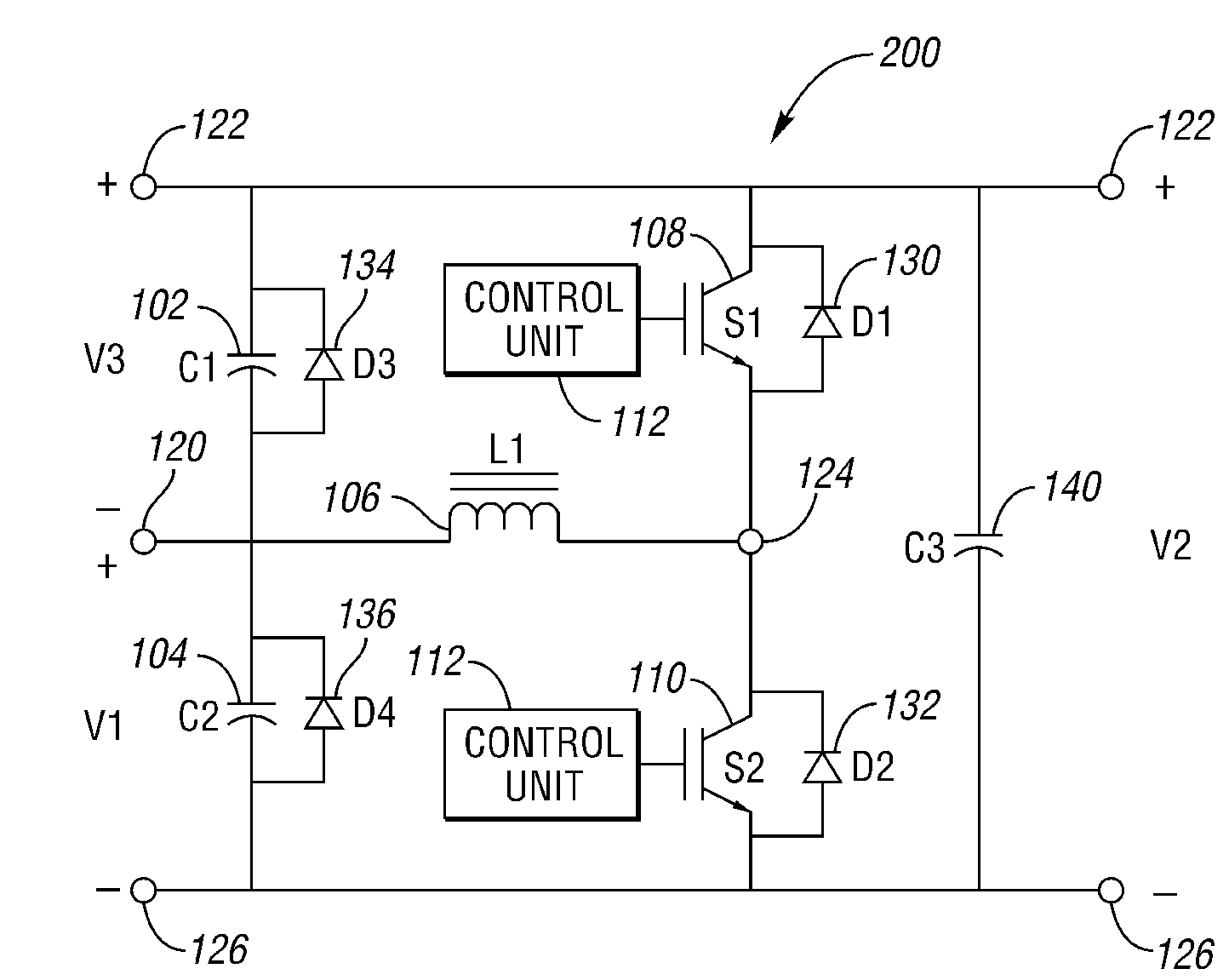
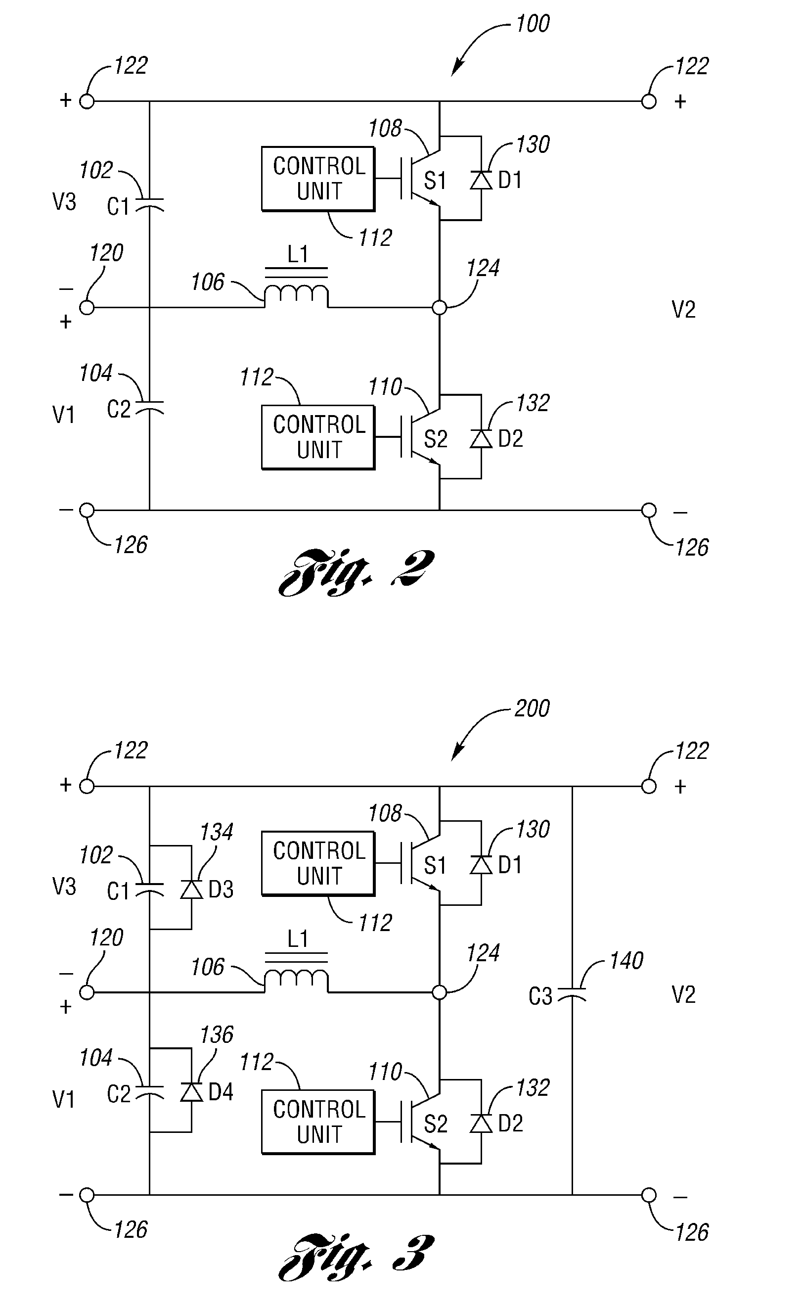
[0017]Referring to FIG. 2, a schematic diagram of a DC-to-DC converter 100 according to at least one embodiment of the present invention is shown. The converter 100 generally comprises a first capacitor (i.e., C1) 102, a second capacitor (i.e., C2) 104, an inductor (i.e., L1) 106, a first switching device (i.e., S1) 108, a second switching device (i.e., S2) 110, and a plurality of nodes, such as a first node 120, a second node 122, a third node 124, and a fourth node 126.

[0018]The first capacitor 102 (i.e., capacitive element), the second capacitor 104, and the inductor 106 (i.e., inductive element) may each include a first and second terminal (i.e., electrical connection point) for coupling (i.e., electrically coupling and / or directly coupling) the corresponding component (i.e., 102, 104, and / or 106) to adjacent components. Similarly, the first 108 and / or second 110 switching devices (i.e., switches) may each include a first and second terminal for coupling the corresponding switch...


PUM


Abstract

A DC-to-DC converter is provided and generally configured for implementation with an electric motor drive system. In at least one embodiment, the DC-to-DC converter includes first and second capacitors, an inductor, and first and second switching devices. The DC-to-DC converter is bi-directional to facilitate voltage transfer therethrough. In at least another embodiment, the electric motor drive system comprises an energy storage device, a drive unit, an electric motor and a bi-directional DC-to-DC converter. The energy storage device includes a positive and a negative terminal. The drive unit includes a first and second terminal. The electric motor is in electrical communication with the drive unit.

Description

BACKGROUND OF THE INVENTION[0001]1. Field of the Invention[0002]The present invention relates generally to a DC-to-DC converter and to an electric motor drive system using the same.[0003]2. Background Art[0004]A DC-to-DC converter generally transforms (i.e., converts) direct current (“DC”) voltage from a first voltage level to a second voltage level. A DC-to-DC converter that transforms a lower input voltage into a higher output voltage (i.e., steps up the voltage) may be referred to as a “boost” converter. Similarly, a DC-to-DC converter that transforms a higher input voltage into a lower output voltage (i.e., steps down the voltage) may be referred to as a “buck” converter.[0005]Referring to FIG. 1(a), a schematic diagram of a conventional bi-directional DC-to-DC converter 10 is shown. In general, Va, Vb and Vc represent three possible terminal voltages, with Vb being greater than or equal to Va (i.e., Vb≧Va), and Vc being equal to the difference between Vb and Va (i.e., Vc=Vb−Va)...

Claims


Application Information

Patent Timeline
Patent Type & Authority Patents(United States)
IPC IPC(8): H02M7/5387G05F1/00
CPCH02M3/158H02M2001/007H02M1/007H02M1/0093H02M3/155H02M3/1582
Inventor CHEN, CHINGCHIDEGNER, MICHAELSANKARAN, VENKATESWA
Owner FORD GLOBAL TECH LLC
Why Eureka
Try Eureka