System and Method for Remotely Monitoring the Operating Life of Electronic Displays

Active Publication Date: 2011-11-17
MFG RESOURCES INT INC
View PDF21 Cites 43 Cited by
  • Summary
  • Abstract
  • Description
  • Claims
  • Application Information

AI Technical Summary

Benefits of technology

[0006]Exemplary embodiments provide communication between one or more displays with a user through an internet or local area network (LAN) connection. In some embodiments this communication would be two-way communication. Electronic data may be

Problems solved by technology

Over many hours of use, even the most reliable electronic displays are know to degrade in performance or possibly have one or more components fail prematurely.
When a display is used for advertising purposes, a sudden failure or degradation in performance can result

Method used


Image

  • System and Method for Remotely Monitoring the Operating Life of Electronic Displays
  • System and Method for Remotely Monitoring the Operating Life of Electronic Displays
  • System and Method for Remotely Monitoring the Operating Life of Electronic Displays

Examples


Example

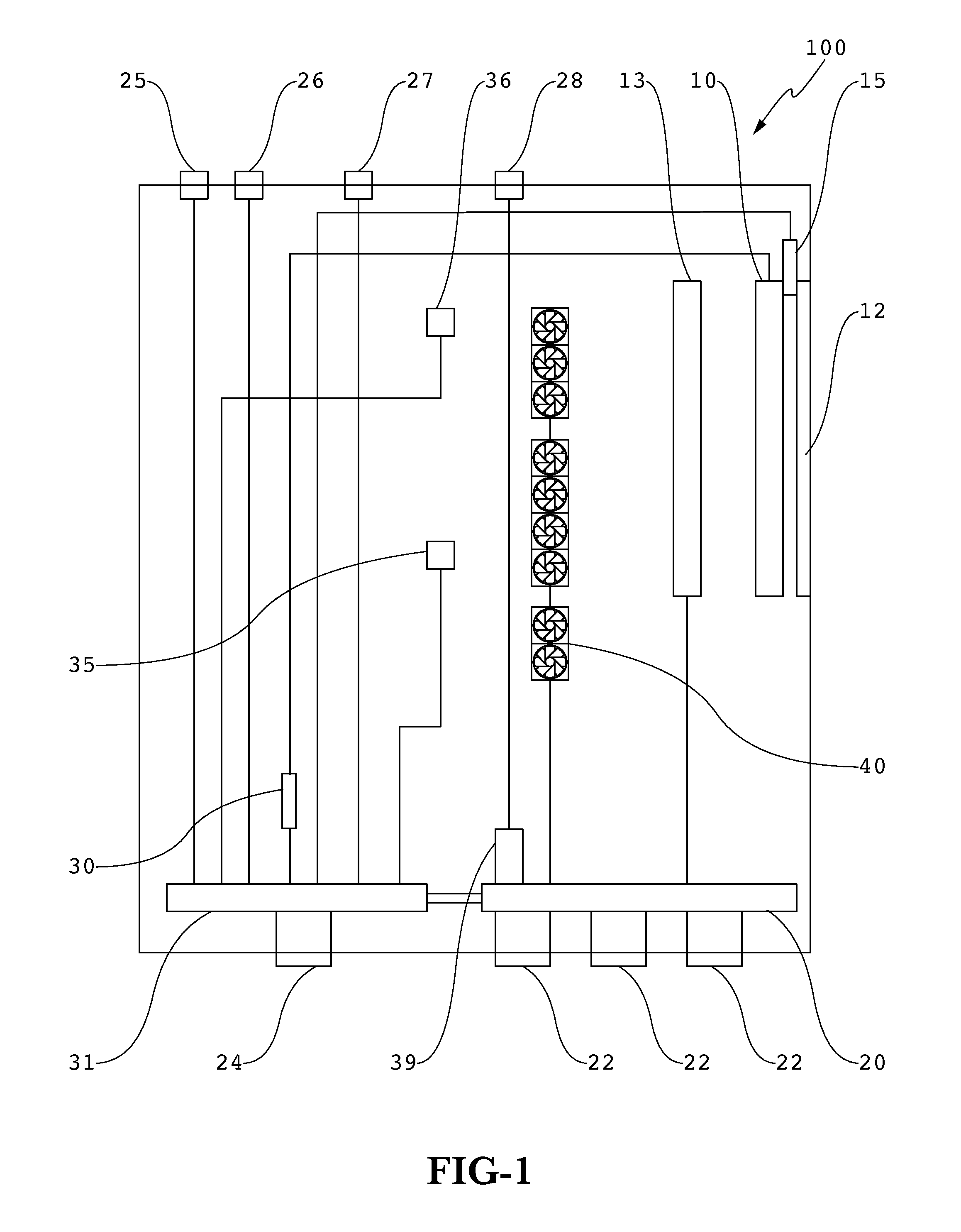
[0014]FIG. 1 shows an electrical block diagram for an exemplary display 100 which contains an embodiment of the display performance monitoring system. A color light sensor 15 may be placed in front of the display assembly 10. In this embodiment, the color light sensor 15 is placed between the display assembly 10 and the front display plate 12 which may protect the display from damage or provide additional optical properties (anti-reflection, polarizing, optical matching, light absorption, etc.). The specific embodiment shown here could be used with an LCD display, where the display assembly 10 may be an LCD stack with an associated backlight assembly 13 placed behind the LCD stack. Obviously, with other embodiments using other types of display assemblies, a backlight assembly 13 may not be necessary. For example, an organic light-emitting diode (OLED), light emitting polymer (LEP), or electroluminescent display may be used as the display assembly 10 where a backlight would not be re...


PUM


Abstract

A system for remotely monitoring and controlling one or more electronic displays containing several hardware components. The components may electronically communicate with a network connection which can be used to establish communication with a local area network and/or the internet. A personal computing device can be used to run a user interface which allows the user to access a wealth of information from the electronic display as well as change controlling software, operating parameters, and check for downtime incidents or failures. Various sensors and measurement devices can be installed within the display to provide the information which may be stored locally or stored remotely for real-time access or on-demand access.

Description

CROSS-REFERENCE TO RELATED APPLICATIONS[0001]This application is a non-provisional of U.S. Application No. 61 / 308,139 filed Feb. 25, 2010 and is hereby incorporated by reference as if fully cited herein. This application is a non-provisional of U.S. Application No. 61 / 312,892 filed Mar. 11, 2010 and is hereby incorporated by reference as if fully cited herein. This application is a continuation in part of U.S. application Ser. No. 12 / 763,797 filed Apr. 20, 2010 and is hereby incorporated by reference as if fully cited herein.TECHNICAL FIELD[0002]Exemplary embodiments generally relate to systems and methods for remotely monitoring and communicating with one or more electronic displays.BACKGROUND OF THE ART[0003]Electronic displays have previously been used predominantly in indoor entertainment applications such as home theatres and bars / restaurants. However, as the performance characteristics and popularity have grown, electronic displays are now being used in many new environments f...

Claims


Application Information

Patent Timeline
IPC IPC(8): G09G3/00G06F3/048
CPCH04L41/22H04N7/173H04N17/004H04N21/41415H04L67/12H04N21/4425H04N21/6582H04N21/812H04N21/4424G06F3/1454G09G5/003G09G2320/08G09G2370/042G09G5/00G09G3/006H04N17/00G09G2360/145
Inventor SCHUCH, JOHNDE LAET, RICK
Owner MFG RESOURCES INT INC
Why Eureka
Try Eureka