Double-stator motor

a double-stator motor and motor technology, applied in the direction of rotating magnets, synchronous machines with stationary armatures, electrical apparatus, etc., can solve the problems of difficult to use these motors in practice, high fabrication cost, and limited installation of motors, so as to reduce the magnetic resistance of the magnetic circuit, suppress the core loss, and reduce the effect of magnetic flux leakag

Inactive Publication Date: 2011-11-24
DENSO CORP
View PDF7 Cites 55 Cited by
  • Summary
  • Abstract
  • Description
  • Claims
  • Application Information

AI Technical Summary

Benefits of technology

[0018]Hence it is desired to provide a double-stator motor at low cost by reducing the number of permanent magnets and to enhance the efficiency in high-speed rotation by suppressing core loss.

Problems solved by technology

These motors have suffered from installation constraints that are ascribed to the purposes of their use.
However, well-known double-stator motors such as the one mentioned above have the following problems (1) to (3) which make it difficult to use these motors in practice.
(1) Fabrication cost is high because of the use of a lot of strong magnets.
(3) The efficiency is poor in high-speed rotation, such as in high-speed cruising.
The reason why a large output cannot be obtained in relation to the quantity of magnets and to the size and volume of the motor is that the cores are saturated and thus magnetic flux leakage is increased.
Therefore, magnetic flux will have a long path and the magnetic resistance will be increased accordingly, leading to the tendency of magnetic flux leakage.
Accordingly, the difference in magnetic potential between portions of the magnetic circuit will become large, further accelerating the tendency of magnetic flux leakage.
The reason why the efficiency is poor in high-speed rotation is that the cores are likely to be saturated, as mentioned above, and thus eddy current loss and hysteresis loss are increased, and, being dependent on the frequency, core loss is increased.
When the number of slots is the same in the first three-phase stator and the second three-phase stator, each slot of the first three-phase stator arranged inside the rotor will have a cross section smaller than that of each slot of the second three-phase stator arranged outside the rotor, making the winding work difficult.
However, concentrated winding has a problem of periodically causing unevenness, i.e. repetition of high magnetic flux density and low magnetic flux density, in adjacently located segment poles.

Method used


Image

  • Double-stator motor
  • Double-stator motor
  • Double-stator motor

Examples


first embodiment

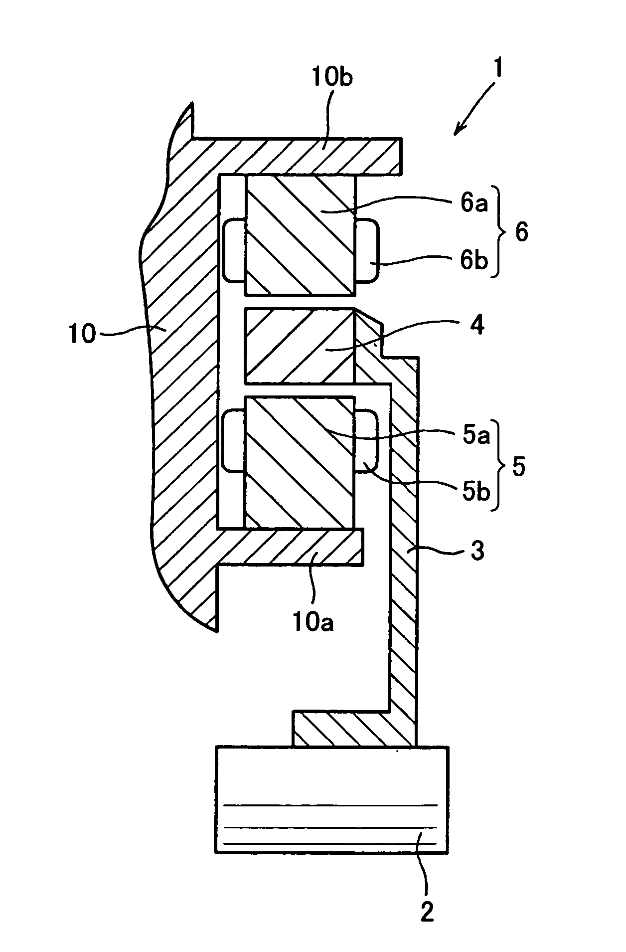
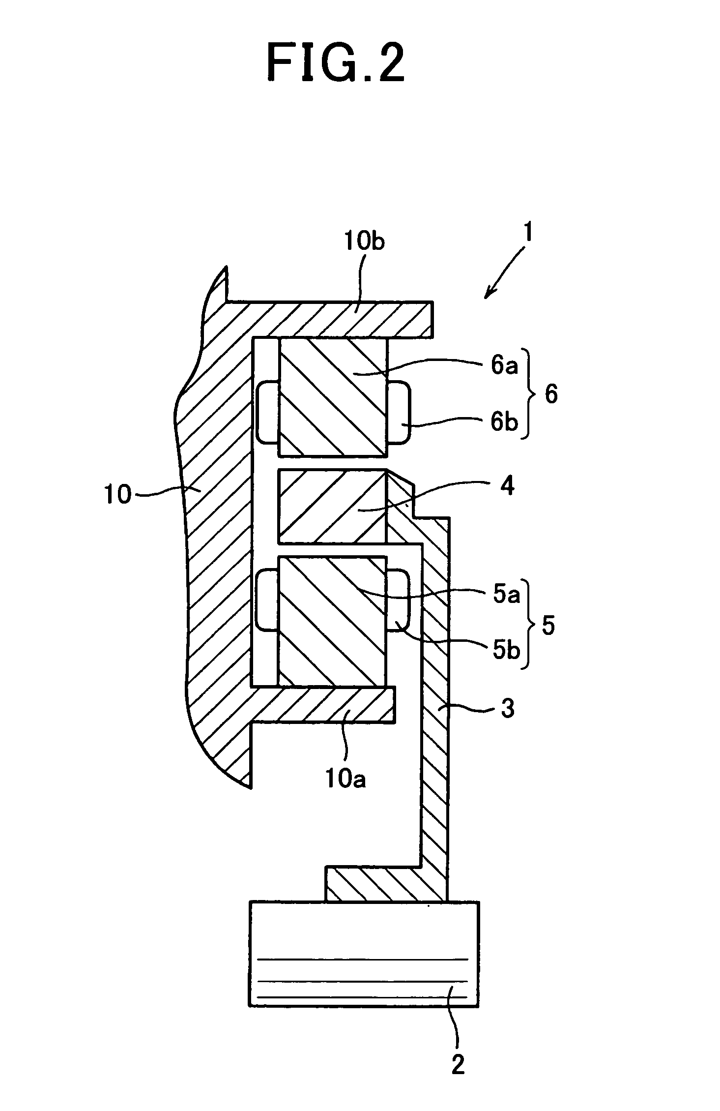
[0061]Referring to FIGS. 2 to 6A and 6B, a first embodiment of the present invention is described. The first embodiment is an example in which a double-stator motor of the present invention is applied to a motor-generator 1 of a hybrid vehicle.

[0062]FIG. 2 is a cross-sectional diagram illustrating a general configuration of the motor-generator 1. FIG. 3 is a partial cross-sectional diagram illustrating the structure of a principal part of a motor, as the motor-generator 1, according to the first embodiment of the present invention.

[0063]As shown in FIG. 2, the motor-generator 1 includes a rotary shaft 2, a disc holder 3, an annular rotor 4, an inner stator 5 (first three-phase stator of the present invention) and an outer stator 6 (second three-phase stator of the present invention). The annular rotor 4 is connected to the rotary shaft 2 via the disc holder 3 so as to be coaxial with the rotary shaft 2. The inner stator 5 is disposed on a radially inner side of the rotor 4. The oute...

second embodiment

[0099]Referring to FIG. 7, hereinafter is described a second embodiment. In the second and the subsequent embodiments, the components identical with or similar to those in the first embodiment are given the same reference numerals for the sake of omitting explanation.

[0100]FIG. 7 is a partial cross-sectional diagram illustrating the structure of a principal part of a motor according to the second embodiment.

[0101]In the second embodiment, the number of slots of the inner stator 5 is smaller than that of the outer stator 6. Also, each slot 5a1 of the inner stator 5 has a cross section larger than in the first embodiment.

[0102]For example, as shown in FIG. 7, six slots are formed for each pole of the outer stator 6 similar to the first embodiment, while three slots are formed for each pole of the inner stator 5, with the cross section of each of the slots 5a1 being designed to be large.

[0103]In the first embodiment exemplified above, the number of slots of the inner and outer stators ...

third embodiment

[0105]Referring to FIGS. 8A, 88 to 10A, 10B, hereinafter is described a third embodiment of the present invention.

[0106]As described in the first embodiment, the inner and outer stators 5 and 6 have an equal electromotive force in the inventive motor. In addition, the inner and outer stators 5 and 6 are arranged face to face sandwiching the segment poles 7. Therefore, two magnetic flux loops are formed in parallel. As a result, the number of gaps for the magnetic flux to pass is only two regarding one magnetic flux loop.

[0107]Thus, compared to the conventional motor, magnetic resistance of the magnetic circuit is reduced. In order to take advantage of this low magnetic resistance, concentrated winding is used in the third embodiment. In an example of the third embodiment, the three-phase coils of the inner and outer stators 5 and 6 are wound, in a concentrated manner, about the core teeth 5a2 and 6a2 formed in the inner and outer stator cores 5a and 6a, respectively.

[0108]Unlike the...


PUM


Abstract

In a double-stator motor has a rotary shaft, an annular rotor is coupled with a rotary shaft. First and second three-phase stators are arranged inside and outside to the rotor in the radial direction and formed to generate first and second rotating magnetic fields in response to three-phase currents, respectively. The rotor has an even number of segment poles made of soft magnetic material and arranged mutually separately at positions of the rotor. The positions are equally distanced apart from the rotary shaft in the radial direction and in the circumferential direction. Each of the first and second three-phase stators has magnetic poles which are the same in the number of poles as the segment poles and the magnetic poles are positioned such that magnetomotive forces from the magnetic poles are faced to each other between the magnetic poles of the first and second three-phase stators.

Description

CROSS-REFERENCE TO RELATED APPLICATION[0001]This application is based on and claims the benefit of priority from earlier Japanese Patent Application No, 2010-116267 filed May 20, 2010, the description of which is incorporated herein by reference.BACKGROUND OF THE INVENTION[0002]1. Technical Field of the Invention[0003]The present invention relates to a double-stator motor having a configuration in which a first three-phase stator is arranged radially inside a rotor and a second three-phase stator is arranged radially outside the rotor.[0004]2. Related Art[0005]Several types of motors, such as motor-generators and in-wheel motors, have been known. A motor-generator is disposed between an engine and a transmission of a vehicle. An in-wheel motor is incorporated into a drive wheel to directly drive the drive wheel. These motors have suffered from installation constraints that are ascribed to the purposes of their use. In other words, due to the limited space of installation, these moto...

Claims


Application Information

Patent Timeline
Patent Type & Authority Applications(United States)
IPC IPC(8): H02K16/04
CPCH02K16/04
Inventor KUSASE, SHINKANAME, YOUSUKESAKURAI, NAOTO
Owner DENSO CORP
Why Eureka
Try Eureka