Maximum Power Point Tracker Bypass

a power point tracker and maximum technology, applied in the direction of electric variable regulation, process and machine control, instruments, etc., can solve problems such as mppt switching loss

Active Publication Date: 2011-11-24
INFINEON TECH AUSTRIA AG
View PDF3 Cites 123 Cited by
  • Summary
  • Abstract
  • Description
  • Claims
  • Application Information

AI Technical Summary

Problems solved by technology

Inevitably, the switching operations result in switching losses in the MPPT.

Method used


Image

  • Maximum Power Point Tracker Bypass
  • Maximum Power Point Tracker Bypass
  • Maximum Power Point Tracker Bypass

Examples


Embodiment Construction

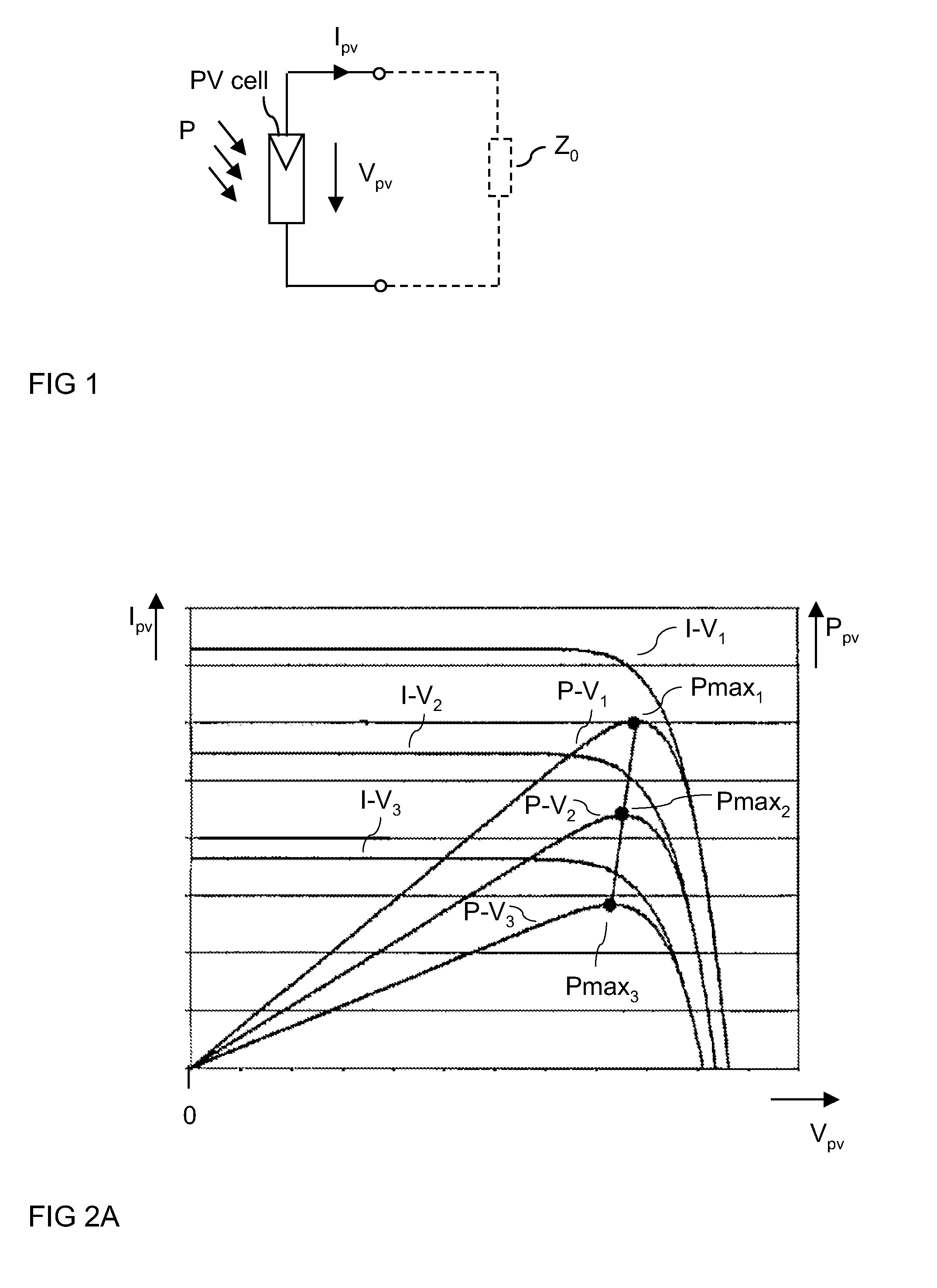
[0024]For a better understanding of the present invention and its implementation principles FIG. 1 schematically illustrates a photovoltaic (PV) cell, that is also known as solar cell, as an example of a DC current source. The PV cell when exposed to solar irradiation provides an output current, that is also referred to as photo current IPV, at an output voltage or photo voltage VPV. The electric power provided by the PV cell is the product of the photo current IPV and the photo voltage VPV. This electric power can be used for supplying an electric load Z0 (illustrated in dashed lines).

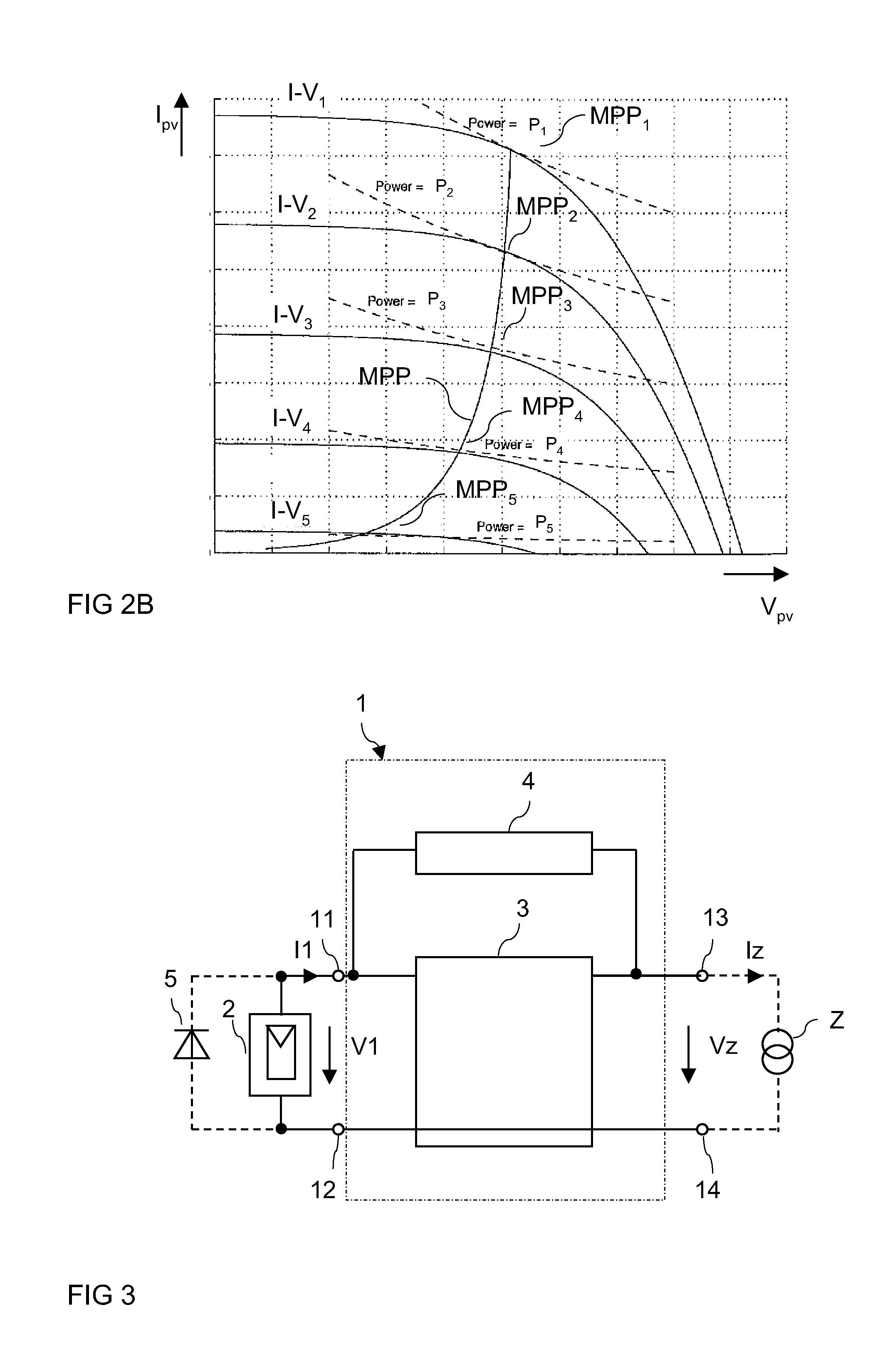
[0025]FIG. 2A schematically illustrates a characteristic curve of a solar cell for different irradiation powers. A characteristic curve illustrates the photo current IPV dependent on the photo voltage VPV. In FIG. 2A three different characteristic curves I-V1, I-V2, I-V3 are illustrated. For a given output voltage the photo current IPV increases with increasing irradiation power. As it can be seen fro...


PUM


Abstract

A circuit arrangement, includes output terminals that provide an output current and input terminals that receive a source current and a source voltage from a DC current source. A maximum power point tracker is coupled between the input terminals and the output terminals and a bypass circuit is coupled between the input terminals and the output terminals. The bypass circuit is configured to enter a bypass state dependent on the output current and dependent on the source current. The source current flows through the bypass circuit in the bypass state.

Description

TECHNICAL FIELD[0001]Embodiments of the present invention relate to a circuit arrangement with a maximum power point tracker.BACKGROUND[0002]With an increasing interest in sustainable energy production there is a focus on using photovoltaic arrays for producing electric power. Photovoltaic (PV) arrays include at least one photovoltaic (PV) cell, which is also known as a solar cell. Since the output voltage of one cell is relatively low, a PV array usually includes a string with a plurality of series connected solar cells or even several such strings connected in parallel.[0003]As it is known, a solar cell, and thus a PV array, acts like a power generator providing a DC output voltage and a DC output current when it is exposed to sunlight. For a given light power received by the PV array there is a range of output currents and a range of corresponding output voltages at which the PV array can be operated. However, there is only one output current and one corresponding output voltage ...

Claims


Application Information

Patent Timeline
Patent Type & Authority Applications(United States)
IPC IPC(8): G05F1/10
CPCG05F1/67H02J3/385G05F5/00Y02E10/58H02M2001/007H02J2300/26H02J3/381Y02E10/56H02M1/007
Inventor DEBOY, GERALD
Owner INFINEON TECH AUSTRIA AG
Why Eureka
Try Eureka